HUFA76445S3S Ver la hoja de datos (PDF) - Fairchild Semiconductor
NГәmero de pieza
componentes DescripciГіn
Fabricante
HUFA76445S3S
Fairchild Semiconductor

HUFA76445S3S Datasheet PDF : 10 Pages
| |||
Data Sheet
HUFA76445P3, HUFA76445S3S
November 2000
File Number 4987
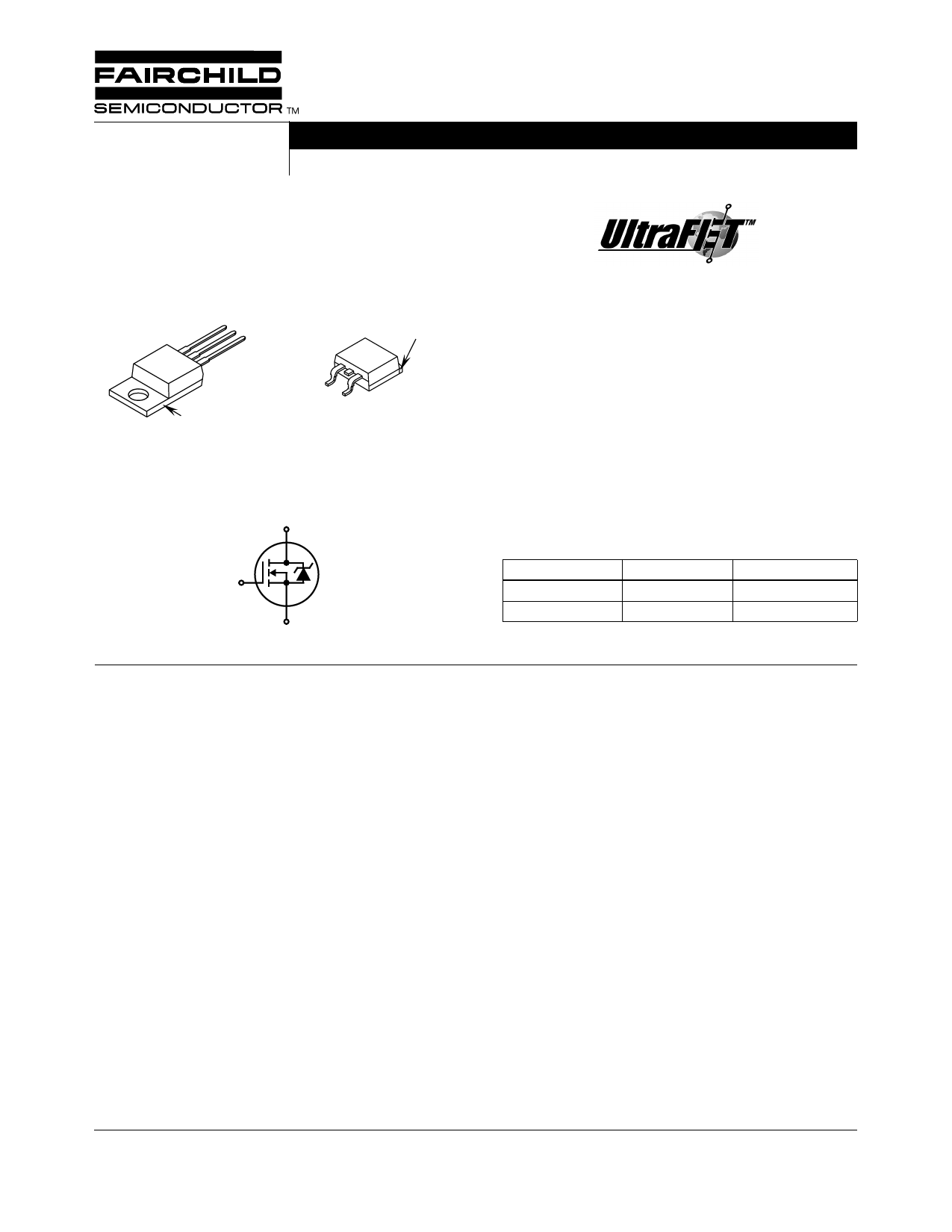
75A, 60V, 0.0075 Ohm, N-Channel, Logic
Level UltraFETВ® Power MOSFET
Packaging
JEDEC TO-220AB
JEDEC TO-263AB
SOURCE
DRAIN
GATE
DRAIN
(FLANGE)
DRAIN
(FLANGE)
HUFA76445P3
GATE
SOURCE
HUFA76445S3S
Symbol
D
G
S
Features
вҖў Ultra Low On-Resistance
- rDS(ON) = 0.0065в„Ұ, VGS = 10V
- rDS(ON) = 0.0075в„Ұ, VGS = 5V
вҖў Simulation Models
- Temperature Compensated PSPICEВ® and SABERв„ў
Electrical Models
- Spice and SABER Thermal Impedance Models
- www.Intersil.com
вҖў Peak Current vs Pulse Width Curve
вҖў UIS Rating Curve
вҖў Switching Time vs RGS Curves
Ordering Information
PART NUMBER
PACKAGE
BRAND
HUFA76445P3
TO-220AB
76445P
HUFA76445S3S
TO-263AB
76445S
NOTE: When ordering, use the entire part number. Add the sufп¬Ғx T
to obtain the variant in tape and reel, e.g., HUFA76445S3ST.
Absolute Maximum Ratings TC = 25oC, Unless Otherwise Speciп¬Ғed
HUFA76445P3, HUFA76445S3S
UNITS
Drain to Source Voltage (Note 1) . . . . . . . . . . . . . . . . . . . . . . . . . . . . . . . . . . . . . . . . . .VDSS
60
V
Drain to Gate Voltage (RGS = 20kв„Ұ) (Note 1) . . . . . . . . . . . . . . . . . . . . . . . . . . . . . . . VDGR
60
V
Gate to Source Voltage . . . . . . . . . . . . . . . . . . . . . . . . . . . . . . . . . . . . . . . . . . . . . . . . . .VGS
Вұ16
V
Drain Current
Continuous (TC = 25oC, VGS = 5V) . . . . . . . . . . . . . . . . . . . . . . . . . . . . . . . . . . . . . . . ID
75
A
Continuous
Continuous
Continuous
(T C
(T C
(T C
=
=
=
21150000oCooCC, V,, VVGGGSSS===1054VV.5))V()F.(i.gF.uig.rue.r.2e.)2. )..
.
.
.
.
.
.
.
.
.
.
.
.
.
.
.
.
.
.
.
.
.
.
.
.
.
.
.
.
.
.
.
.
.
.
.
.
.
.
.
.
.
.
.
.
.
.
.
.
.
.
.
.
.
.
.
.
.
.
.
.
.
.
.
.
.
.
.
.
.
.
.
.
.
.
.
.
.
.
.
.
.
.
.
.
.
.
.
ID
ID
ID
75
75
75
A
A
A
Pulsed Drain Current . . . . . . . . . . . . . . . . . . . . . . . . . . . . . . . . . . . . . . . . . . . . . . . . . . IDM
Figure 4
Pulsed Avalanche Rating . . . . . . . . . . . . . . . . . . . . . . . . . . . . . . . . . . . . . . . . . . . . . . . . UIS
Figures 6, 17, 18
Power Dissipation . . .
Derate Above 25oC
.
.
.
.
.
.
.
.
.
.
.
.
.
.
.
.
.
.
.
.
.
.
.
.
.
.
.
.
.
.
.
.
.
.
.
.
.
.
.
.
.
.
.
.
.
.
.
.
.
.
.
.
.
.
.
.
.
.
.
.
.
.
.
.
.
.
.
.
.
.
.
.
.
.
.
.
.
.
.
.
.
.
.
.
.
.
.
.
.
.
.
.
.
.
.
.
.
.
.
.
.
.
.
.
PD
..
Operating and Storage Temperature . . . . . . . . . . . . . . . . . . . . . . . . . . . . . . . . . . . . TJ, TSTG
Maximum Temperature for Soldering
Leads at 0.063in (1.6mm) from Case for 10s. . . . . . . . . . . . . . . . . . . . . . . . . . . . . . . . . TL
Package Body for 10s, See Techbrief TB334 . . . . . . . . . . . . . . . . . . . . . . . . . . . . . . . Tpkg
NOTES:
1. TJ = 25oC to 150oC.
310
2.08
-55 to 175
300
260
W
W/oC
oC
oC
oC
CAUTION: Stresses above those listed in вҖңAbsolute Maximum RatingsвҖқ may cause permanent damage to the device. This is a stress only rating and operation of the
device at these or any other conditions above those indicated in the operational sections of this speciп¬Ғcation is not implied.
This product has been designed to meet the extreme test conditions and environment demanded by the automotive industry. For a copy
of the requirements, see AEC Q101 at: http://www.aecouncil.com/
Reliability data can be found at: http://www.mtp.intersil.com/automotive.html.
All Intersil semiconductor products are manufactured, assembled and tested under ISO9000 and QS9000 quality systems certification.
В©2001 Fairchild Semiconductor Corporation
HUFA76445P3, HUFA76445S3S Rev. A
Share Link: