DS2223T Ver la hoja de datos (PDF) - Dallas Semiconductor -> Maxim Integrated
Número de pieza
componentes Descripción
Fabricante
DS2223T Datasheet PDF : 10 Pages
| |||
DS2223/DS2224
1–WIRE INTERFACE
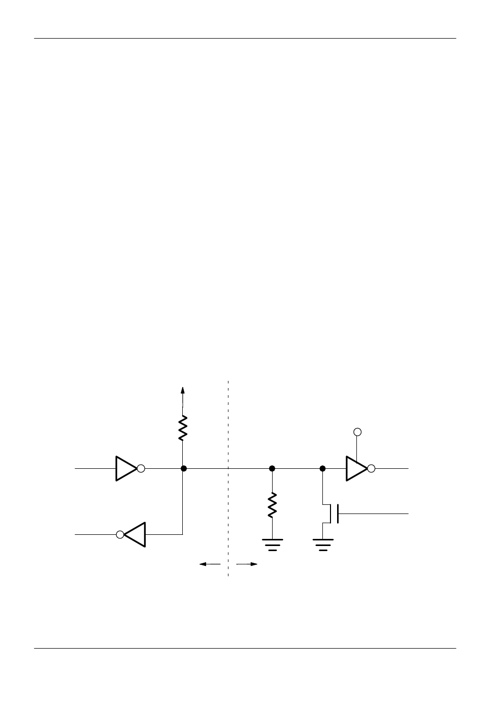
The 1–Wire interface has only a single line by definition;
it is important that host and EconoRAM be able to drive it
at the appropriate time. The EconoRAM is an open drain
part with an internal circuit equivalent to that shown in
Figure 8. The host can be the same equivalent circuit. If
a bidirectional pin is not available, separate output and
input pins can be tied together.
The 1–Wire interface requires a pull–up resistor with a
value of approximately 5 kΩ to system VCC on the data
signal line. The EconoRAM has an internal open–drain
driver with a 500 kΩ pull–down resistor to ground. The
open–drain driver allows the EconoRAM to be powered
by a small standby energy source, such as a single 1.5
volt alkaline battery, and still have the ability to produce
CMOS/TTL output levels. The pull–down resistor holds
the DQ pin at ground when the EconoRAM is not con-
nected to the host.
APPLICATION EXAMPLES
EconoRAMs are extremely conservative with power.
Data can be retained in these small memories for as
long as a month using the energy stored in a capacitor.
Data is retained as long as the voltage on the VCC pin of
the EconoRAM (VCAP) is at least 1.2 volts. A typical cir-
cuit is shown in Figure 9.
When VCC is applied, capacitor C1 is charged and the
EconoRAM receives power directly from VCC. After
power is removed, the diode CR1 prevents current from
leaking back into the system, keeping the capacitor
charged.
In the standby mode, the EconoRAM typically con-
sumes only 12 nA at 25°C. However, the power–down
process of the system can cause a slightly higher cur-
rent drain. This is due to the fact that as system power
ramps down, the signal attached to the DQ pin of the
EconoRAM transitions slowly through the linear region,
while the VCAP voltage remains at its initial value. While
in this region, the part draws more current as a function
of the DQ pin voltage (see Figure 10).
The data retention time can be estimated with the aid of
Figure 11. In this figure, the vertical axis represents the
value of the capacitor C1; the horizontal axis is the data
retention time in hours. The two curves represent initial
VCAP voltages of 3 and 5 volts. These curves are based
on the assumption that the time the DQ pin is in the lin-
ear region is less than 100 ms.
HOST TO ECONORAM INTERFACE Figure 8
VCC
5 kΩ
VCC
TX
OPEN
DRAIN
RX
500 kΩ
RX
TX
100 OHM MOSFET
HOST ECONORAM
020698 6/10
6
Share Link: 