NE568 Ver la hoja de datos (PDF) - Philips Electronics
Número de pieza
componentes Descripción
Fabricante
NE568 Datasheet PDF : 9 Pages
| |||
Philips Semiconductors
150MHz phase-locked loop
Product specification
NE/SA568A
C9
+
1
2p (50)
(fO)
F
At 70MHz, the calculated value is 45pF. Empirical results with the
test and application board were improved when a 47pF capacitor
was used.
The natural frequency for the loop filter is set by C10 and R1. If the
center frequency of the loop is 70MHz and the full demodulated
bandwidth is desired, i.e., fBW = fO/7 = 10MHz, and a value for R1 is
chosen, the value of C10 can be calculated.
Also,
C10
+
2p
1
R1
fBW
F
C11
+
1
2p350WfBW(Hz)
This capacitance determines the signal bandwidth of the output
buffer amplifier. (For further inofrmation see Philips application note
AN1881 “The NE568A Phase Locked Loop as a Wideband Video
Demodulator”.
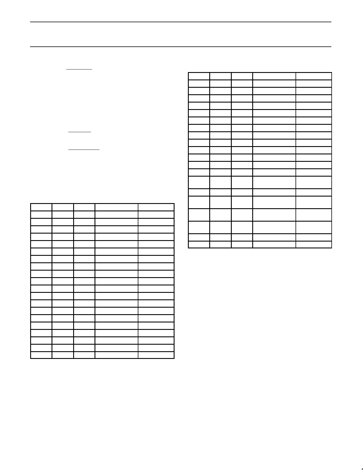
Parts List and Layout 40MHz Application NE568AD
C1
100nF ±10% Ceramic chip
C21
18pF ±2% Ceramic chip
1206
0805
C22
16pF ±2% Ceramic ORChip
C3
100nF ±10% Ceramic chip
1206
C4
100nF ±10% Ceramic chip
1206
C5
6.8µF ±10% Tantalum
35V
C6
100nF ±10% Ceramic chip
1206
C7
100nF ±10% Ceramic chip
1206
C8
100nF ±10% Ceramic chip
1206
C9
47pF ±2% Ceramic chip
0805 or 1206
C10
560pF ±2% Ceramic chip
0805 or 1206
C11
47pF ±2% Ceramic chip
0805 or 1206
C12
100nF ±10% Ceramic chip
1206
C13
100nF ±10% Ceramic chip
1206
R1
27Ω ±10% Chip CR32
1/4W
R2
1.2kΩ
Trim pot
R33
43Ω ±10% Chip CR32
R44
3.9kΩ ±10% Chip CR32
1/4W
1/4W
R53
50Ω ±10% Chip CR32
1/4W
RFC15 10µH ±10% Surface mount
RFC25 10µH ±10% Surface mount
NOTES:
1. 18pF with Pin 12 ground and Pin 13 no connect (open).
2. C2 + CSTRAY = 16pF for temperature-compensated configuration
with R4 = 3.9kΩ.
3. For 50Ω setup. R1 = 62Ω, R3 = 75Ω for 75Ω application.
4. For test configuration R4 = 0Ω (GND) and C2 = 18pF.
5. 0Ω chip resistors (jumpers) may be substituted with minor degra-
dation of performance.
Parts List and Layout 70MHz Application NE568AN
C1
C21
C22
C3
C4
C5
C6
C7
C8
C9
C10
C11
C12
C13
R1
R2
R33
R44
R53
RFC1
RFC2
100nF
18pF
16pF
100nF
100nF
6.8µF
100nF
100nF
100nF
47pF
560pF
47pF
100nF
100nF
27Ω
1.2kΩ
43Ω
3.9kΩ
50Ω
10µH
10µH
±10%
±2%
±2%
±10%
±10%
±10%
±10%
±10%
±10%
±2%
±2%
±2%
±10%
±10%
±10%
±10%
±10%
±10%
±10%
±10%
Ceramic chip
Ceramic chip
Ceramic chip
Ceramic chip
Ceramic chip
Tantalum
Ceramic chip
Ceramic chip
Ceramic chip
Ceramic chip
Ceramic chip
Ceramic chip
Ceramic chip
Ceramic chip
Ceramic chip
CR32
Trim pot
Ceramic chip
CR32
Ceramic chip
CR32
Ceramic chip
CR32
Surface mount
Surface mount
50V
50V
0805
50V
50V
35V
50V
50V
50V
50V
50V
50V
50V
50V
1/4W
1/4W
1/4W
1/4W
NOTES:
1. 18pF with Pin 12 ground and Pin 13 no connect (open).
2. C2 + CSTRAY = 16pF for temperature-compensated configuration
with R4 = 3.9kΩ.
3. For 50Ω setup. R1 = 62Ω, R3 = 75Ω for 75Ω application.
4. For test configuration R4 = 0Ω (GND) and C2 = 18pF.
1996 Feb 1
4
Share Link: 