NE568A Ver la hoja de datos (PDF) - Philips Electronics
Número de pieza
componentes Descripción
Fabricante
NE568A Datasheet PDF : 9 Pages
| |||
Philips Semiconductors
150MHz phase-locked loop
Product specification
NE/SA568A
VCC
1
VCC2
C1
2 GND2
3 GND1
RFC1
4 TCAP1
C2
5
TCAP2
6 GND1
C8
7
VCC1
C3
8
C5
C6 RFC2
C4
REFBYP
9 PNPBYP
10
INPBYP
C7
LF1 20
LF2 19
LF3 18
LF4 17
R1
C10
C9
R2
16
FREQADJ
OUTFILT 15 C11
14 C12
R3
VOUT
13
R4
TCADJ2
VOUT
TCADJ1 12
11 C13
VIN
VIN
R5
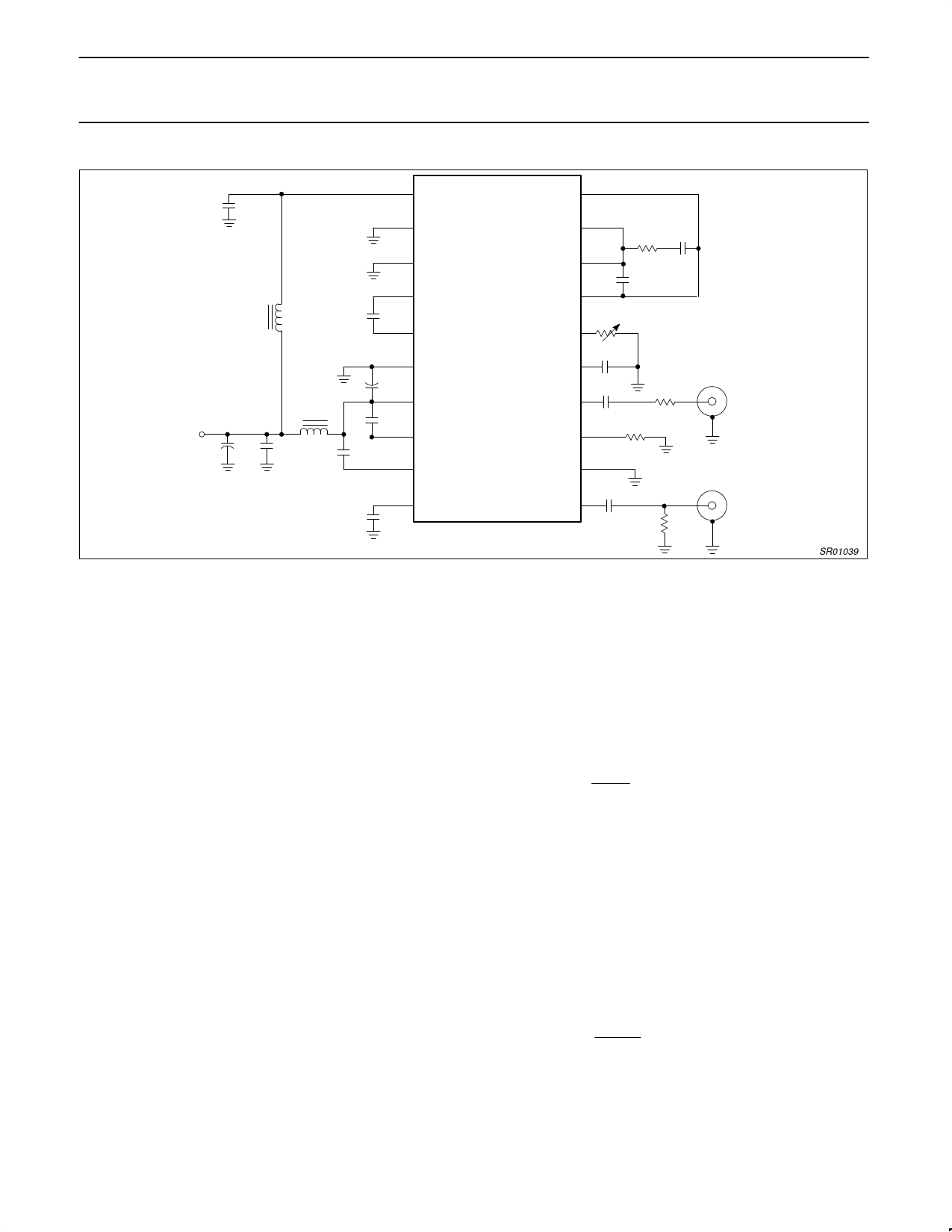
Figure 3. Test Circuit for AC Parameters
SR01039
FUNCTIONAL DESCRIPTION
The NE568A is a high-performance phase-locked loop (PLL). The
circuit consists of conventional PLL elements, with special circuitry
for linearized demodulated output, and high-frequency performance.
The process used has NPN transistors with fT > 6GHz. The high
gain and bandwidth of these transistors make careful attention to
layout and bypass critical for optimum performance. The
performance of the PLL cannot be evaluated independent of the
layout. The use of the application layout in this data sheet and
surface-mount capacitors are highly recommended as a starting
point.
The input to the PLL is through a limiting amplifier with a gain of 200.
The input of this amplifier is differential (Pins 10 and 11). For
single-ended applications, the input must be coupled through a
DC-blocking capacitor with low impedance at the frequency of
interest. The single-ended input is normally applied to Pin 11 with
Pin 10 AC-bypassed with a low-impedance capacitor. The input
impedance is characteristically slightly above 500Ω. Impedance
match is not necessary, but loading the signal source should be
avoided. When the source is 50 or 75Ω, a DC-blocking capacitor is
usually all that is needed.
Input amplification is low enough to assure reasonable response
time in the case of large signals, but high enough for good AM
rejection. After amplification, the input signal drives one port of a
multiplier-cell phase detector. The other port is driven by the
current-controlled oscillator (ICO). The output of the phase
comparator is a voltage proportional to the phase difference of the
input and ICO signals. The error signal is filtered with a low-pass
filter to provide a DC-correction voltage, and this voltage is
converted to a current which is applied to the ICO, shifting the
frequency in the direction which causes the input and ICO to have a
90° phase relationship.
The oscillator is a current-controlled multivibrator. The current
control affects the charge/discharge rate of the timing capacitor. It is
common for this type of oscillator to be referred to as a
voltage-controlled oscillator (VCO), because the output of the phase
comparator and the loop filter is a voltage. To control the frequency
of an integrated ICO multivibrator, the control signal must be
conditioned by a voltage-to-current converter. In the NE568A,
special circuitry predistorts the control signal to make the change in
frequency a linear function over a large control-current range.
The free-running frequency of the oscillator depends on the value of
the timing capacitor connected between Pins 4 and 5. The value of
the timing capacitor depends on internal resistive components and
current sources. When R2 = 1.2kΩ and R4 = 0Ω, a very close
approximation of the correct capacitor value is:
where
C*
+
0.0014
fO
F
C * + C2 ) CSTRAY
The temperature-compensation resistor, R4, affects the actual value
of capacitance. This equation is normalized to 70MHz. See 10 for
correction factors.
The loop filter determines the dynamic characteristics of the loop. In
most PLLs, the phase detector outputs are internally connected to
the ICO inputs. The NE568A was designed with filter output to input
connections from Pins 20 (φ DET) to 17 (ICO), and Pins 19 (φ DET)
to 18 (ICO) external. This allows the use of both series and shunt
loop-filter elements. The loop constratints are:
KO + 0.12VńRadian (Phase Detector Constant)
KO
+
4.2 @ 109
Radians
V–sec
(ICO Constant) at 70MHz
The loop filter determines the general characteristics of the loop.
Capacitors C9, C10, and resistor R1, control the transient output of
the phase detector. Capacitor C9 suppresses 70MHz feedthrough
by interaction with 100Ω load resistors internal to the phase
detector.
1996 Feb 1
3
Share Link: 