AT49BV004-12TC Ver la hoja de datos (PDF) - Atmel Corporation
Número de pieza
componentes Descripción
Fabricante
AT49BV004-12TC Datasheet PDF : 15 Pages
| |||
AT49BV004(T)/4096A(T)
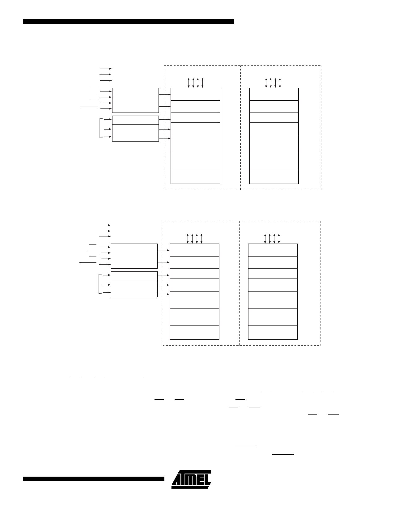
AT49BV004(T) Block Diagram
VCC
VPP
GND
OE
WE
CE
RESET
ADDRESS
INPUTS
CONTROL
LOGIC
Y DECODER
X DECODER
AT49BV004
DATA INPUTS/OUTPUTS
I/O0 - I/O7
AT49BV004T
DATA INPUTS/OUTPUTS
I/O0 - I/O7
INPUT/OUTPUT
BUFFERS
PROGRAM DATA
LATCHES
Y-GATING
MAIN MEMORY
(480K BYTES)
PARAMETER
BLOCK 2
8K BYTES
PARAMETER
BLOCK 1
8K BYTES
BOOT BLOCK
16K BYTES
7FFFF
08000
07FFF
06000
05FFF
04000
03FFF
00000
INPUT/OUTPUT
BUFFERS
PROGRAM DATA
LATCHES
Y-GATING
BOOT BLOCK
16K BYTES
PARAMETER
BLOCK 1
8K BYTES
PARAMETER
BLOCK 2
8K BYTES
MAIN MEMORY
480K BYTES
7FFFF
7C000
7BFFF
7A000
79FFF
78000
77FFF
00000
AT49BV4096A(T) Block Diagram
VCC
VPP
GND
AT49BV4096A
DATA INPUTS/OUTPUTS
I/O0 - I/O7 – I/O0 - I/O15
AT49BV4096AT
DATA INPUTS/OUTPUTS
I/O0 - I/O7 – I/O0 - I/O15
OE
WE
CE
RESET
ADDRESS
INPUTS
CONTROL
LOGIC
Y DECODER
X DECODER
INPUT/OUTPUT
BUFFERS
PROGRAM DATA
LATCHES
Y-GATING
MAIN MEMORY
(240K WORDS)
PARAMETER
BLOCK 2
4K WORDS
PARAMETER
BLOCK 1
4K WORDS
BOOT BLOCK
8K WORDS
3FFFF
04000
03FFF
03000
02FFF
02000
01FFF
00000
INPUT/OUTPUT
BUFFERS
PROGRAM DATA
LATCHES
Y-GATING
BOOT BLOCK
8K WORDS
PARAMETER
BLOCK 1
4K WORDS
PARAMETER
BLOCK 2
4K WORDS
MAIN MEMORY
(240K WORDS)
3FFFF
3E000
3DFFF
3D000
3CFFF
3C000
3BFFF
00000
Device Operation
READ: The AT49BV004(T)/4096A(T) is accessed like an
EPROM. When CE and OE are low and WE is high, the
data stored at the memory location determined by the
address pins is asserted on the outputs. The outputs are
put in the high impedance state whenever CE or OE is
high. This dual-line control gives designers flexibility in pre-
venting bus contention.
COMMAND SEQUENCES: When the device is first pow-
ered on it will be reset to the read or standby mode
depending upon the state of the control line inputs. In order
to perform other device functions, a series of command
sequences are entered into the device. The command
sequences are shown in the Command Definitions table
(I/O8 - I/O15 are don’t care inputs for the command codes).
The command sequences are written by applying a low
pulse on the WE or CE input with CE or WE low (respec-
tively) and OE high. The address is latched on the falling
edge of CE or WE, whichever occurs last. The data is
latched by the first rising edge of CE or WE. Standard
microprocessor write timings are used. The address loca-
tions used in the command sequences are not affected by
entering the command sequences.
RESET: A RESET input pin is provided to ease some sys-
tem applications. When RESET is at a logic high level, the
3
Share Link: 