AM24LC08IN Ver la hoja de datos (PDF) - Anachip Corporation
Número de pieza
componentes Descripción
Fabricante
AM24LC08IN Datasheet PDF : 10 Pages
| |||
2-Wire Serial 8K-Bit (1024 x 8) CMOS Electrically Erasable PROM
ATC
AM24LC08
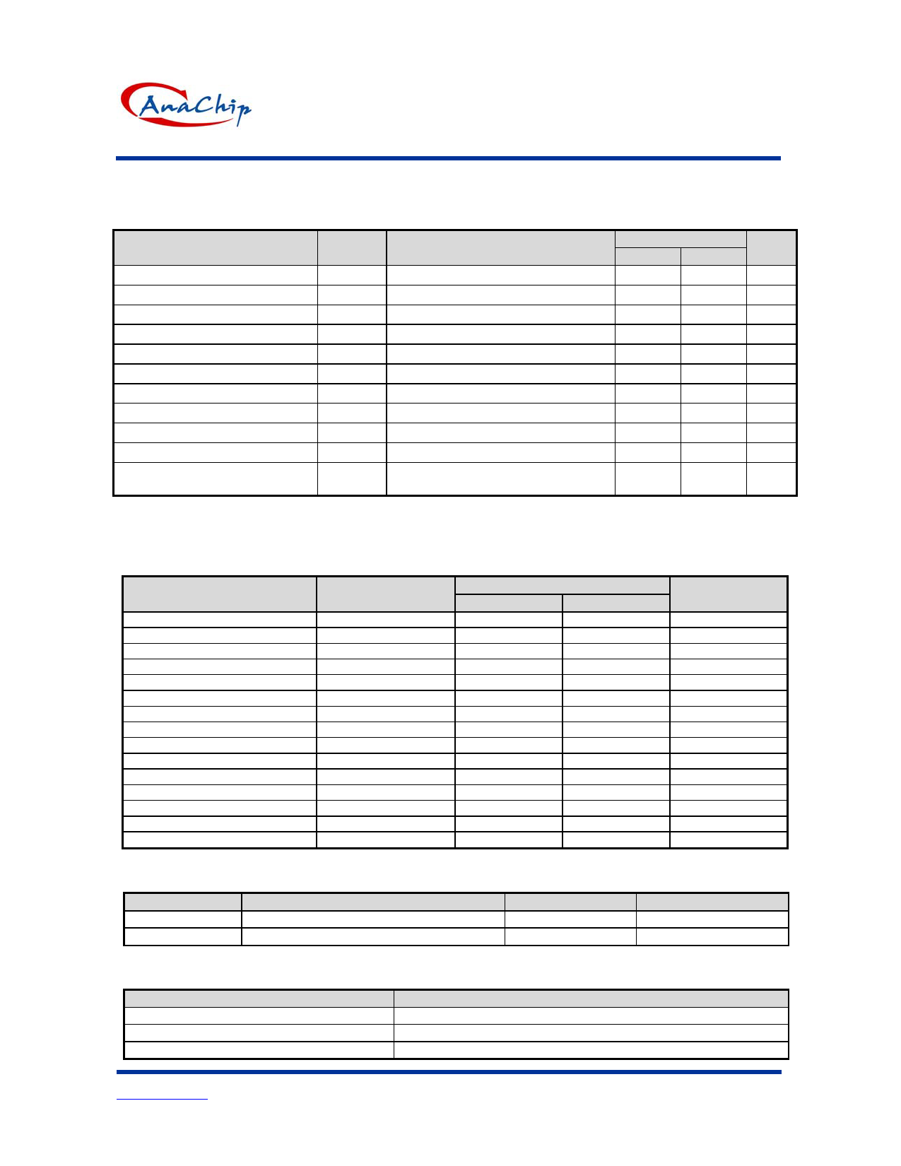
Electrical Characteristics
DC Electrical Characteristics (Vcc =2.7~5.5V, Ta = 25oC )
Parameter
Symbol
Conditions
Operating Current (Program) ** ICC1 SCL = 100KHZ CMOS Input Levels
Operating Current (Read) **
ICC2 SCL = 100KHZ CMOS Input Levels
Standby Current
ISB1 SCL=SDA=0V, Vcc=5V
Standby Current
ISB2 SCL=SDA=0V, Vcc=3V
Input Leakage
IIL VIN = 0 V to VCC
Output Leakage
IOL VOUT = 0 V to Vcc
Input Low Voltage**
VIL
Input High Voltage**
VIH
Output Low Voltage
VOL1 IOL = 2.1mA TTL
Output Low Voltage
VCC Lockout Voltage
VOL2 IOL = 10uA CMOS
VLK
Programming Command Can Be
Executed
Note ** : ICC1, ICC2, VIL min and VIH max are for reference only and are not tested.
AM24LC08
Min
Max
—
3
—
200
—
10
—
1
-1
+1
-1
+1
-0.1 Vcc x 0.3
Vcc x 0.7 VCC+ 0.2
—
0.4
—
0.2
Default
—
Units
mA
µA
µA
µA
µA
µA
V
V
V
V
V
Switching Characteristics (Under Operating Conditions)
AC Electrical Characteristics (Vcc =2.7~5.5V)
Parameter
Symbol
Clock frequency
Fscl
Clock high time
Thigh
Clock low time
Tlow
SDA and SCL rise time**
Tr
SDA and SCL fall time**
Tf
START condition hold time
Thd:Sta
START condition setup time
Tsu:Sta
Data input hold time
Thd:Dat
Data input setup time
Tsu:Dat
STOP condition setup time
Tsu:Sto
Output valid from clock
Taa
Bus free time **
Tbuf
Data out hold time
Tdh
Write cycle time
Twr
5V, 25ºC, Byte Mode
Endurance**
Note **: This parameter is characterized and is not 100% tested.
AM24LC08
Min
Max
0
100
4000
—
4700
—
—
1000
—
300
4000
—
4700
—
0
—
250
—
4000
—
300
3500
4700
—
300
—
—
10
1M
—
Units
kHz
ns
ns
ns
ns
ns
ns
ns
ns
ns
ns
ns
ns
ms
write cycles
Pin Capacitance ** ( Ta= 25°C, f=250KHz )
Symbol
Parameter
COUT
Output capacitance
CIN
Input capacitance
Note ** : This parameter is characterized and is not 100% tested.
Max
Units
5
pF
5
pF
AC. Conditions of Test
Input Pulse Levels
Input Rise and Fall times
Input and Output Timming level
Output Load
Vcc x 0.1 to Vcc x 0.9
10 ns
Vcc x 0.5
1 TTL Gate and CL = 100pf
Anachip Corp.
www.anachip.com.tw
Rev. A1 Oct 20, 2003
3/10
Share Link: 