SSD0858Z Ver la hoja de datos (PDF) - Solomon Systech
Número de pieza
componentes Descripción
Fabricante
SSD0858Z Datasheet PDF : 45 Pages
| |||
6.10 ROW0 – ROW63
These pins provide the row driving signal ROW0 - ROW63 to the LCD panel. See Figure 5 or Figure 7
about the COM signal mapping in different multiplex ratio N.
6.11 ICONS
This pin is the special icon line ROW signal output.
6.12 COL0 – COL103
These pins provide the LCD column driving signal. Their voltage level is VSS during sleep mode.
6.13 CL
This pin is the external clock input for the device, which is enabled by using an extended command.
Under normal operation, this pin should be left opened and internal oscillator will be used after power on
reset.
6.14 M
This pin is used for cascade purpose only. Under normal operation, it should be left open.
6.15 MID0~MID2
These pins are used for setting the ID code of LCD panel manufacturer. These pins should be connected
to VSS or VDD when NOT IN USE.
6.16 SYNC
This pin is used for cascade purpose only. Under normal operation, it should be left open.
6.17 MODE
This pin is used for setting the display size.
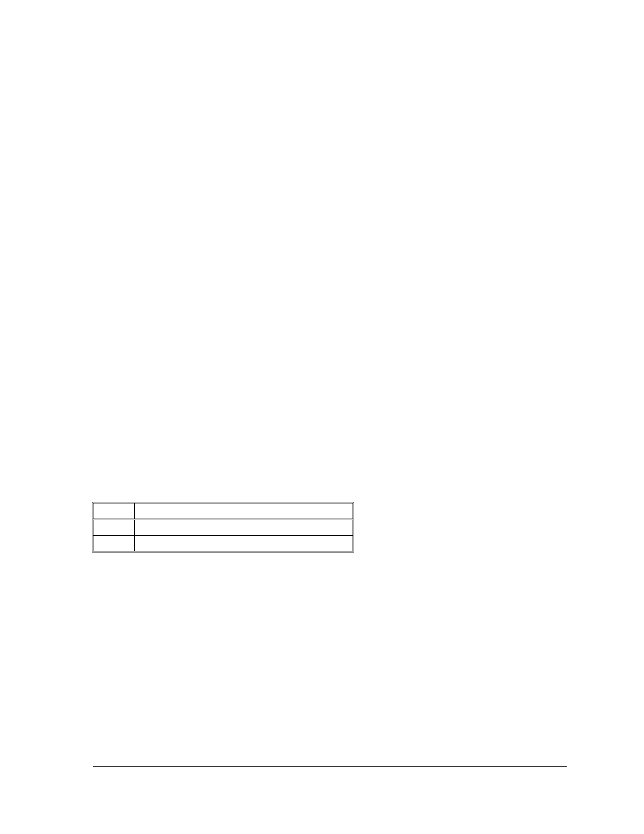
Table 4 – Mode setting
MODE
H
L
Remarks:
SSD0858 96x65 display mode
SSD0858 104x65 display mode
6.18 TEST_IN0~7
These pins are used for internal only. TEST_IN0~5 & 7 should be connected to VSS and TEST_IN6
should be connected to VDD.
6.19 TEST0~19
These pins are used for internal only and should be left open, any connection is not allowed.
6.20 Dummy
There are the floating dummy pads without any internal circuitry connection.
SSD0858
Rev 1.0
11/2002
10
SOLOMON
Share Link: 