IMP38C42 Ver la hoja de datos (PDF) - IMP, Inc
Número de pieza
componentes Descripción
Fabricante
IMP38C42 Datasheet PDF : 10 Pages
| |||
IMP38C/HC/42/3/4/5
Absolute Maximum Ratings
VCC Supply Voltage . . . . . . . . . . . . . . . . . . . . . . 20V
VCC Supply Current . . . . . . . . . . . . . . . . . . . . . . 30mA
IOUT Current . . . . . . . . . . . . . . . . . . . . . . . . . . . . 1.0A
Current-Sense and Feedback Inputs . . . . . . . . 0.3V to 5.5V
Operation Junction Temperature . . . . . . . . . . . +150°C
Storage Temperature . . . . . . . . . . . . . . . . . . . . . – 65°C to +150°C
Lead Soldering Temperature (10 seconds) . . . +300°C
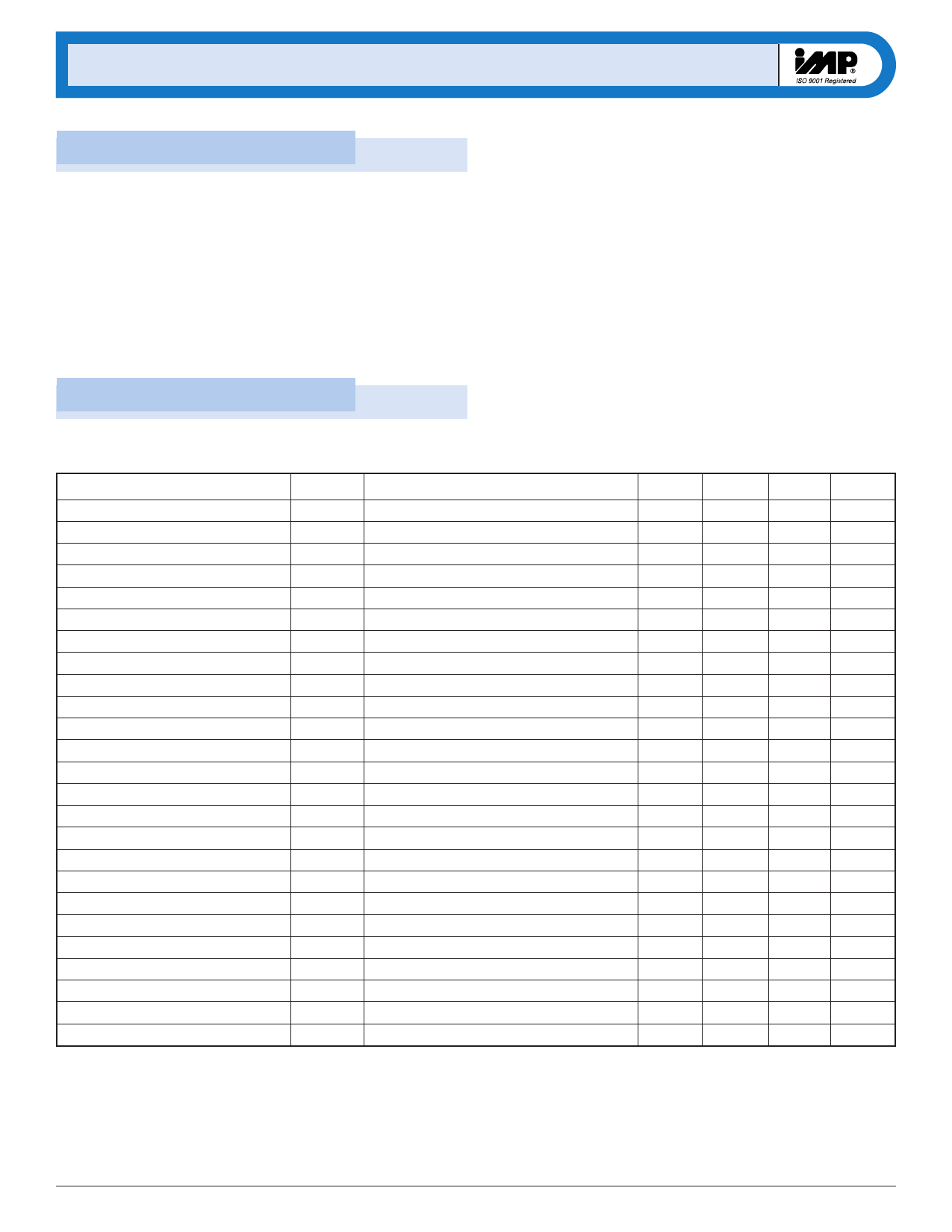
Electrical Characteristics
Package Thermal Resistance
8-Pin Plastic DIP (θJA) . . . . . . . . . . . . . . . . . 125°C/W
8-Pin MicroSO (θJA) . . . . . . . . . . . . . . . . . . . 250°C/W
8-Pin SO (θJA) . . . . . . . . . . . . . . . . . . . . . . . . 170°C/W
14-Pin Plastic DIP (θJA) . . . . . . . . . . . . . . . . 90°C/W
14-Pin SO (θJA) . . . . . . . . . . . . . . . . . . . . . . . 145°C/W
Note: All voltages are referenced to GND.
These are stress ratings only and functional operation is not
implied. Exposure to absolute maximum ratings for prolonged
time periods may affect device reliability.
Unless otherwise noted, VCC = 15V, RT = 10kΩ and CT = 3.3nF. Specifications are over the – 40°C to +85°C ambient temperature range.
Bold/blue specifications indicate enhanced performance features.
Parameter
Reference
Output voltage
Line Regulation
Load Regulation
Temperature Stability
Total Reference Variation
Output Noise Voltage
Long Term Stability
Output Short Circuit
Oscillator Section
Initial Accuracy
Voltage Stability
Temperature Stability
Discharge Current
Amplitude peak-to-peak
Error Amplifier Section
Input Voltage
Input Bias Current
Open Loop Gain
Unity Gain Bandwidth
Power Supply Rejection Ratio
Output Sink Current
Output Source Current
VOUT High
VOUT Low
Symbol Conditions
VREF
TCREF
VN
ISC
TA = +25°C, IO = 1mA
12V ≤ VCC ≤ 18V, IOUT = 5µA
1mA ≤ IO ≤ 20mA
Note 1
Line, Load, Temperature, Note 1
10Hz ≤ f ≤ 10kHz, TA = +25°C, Note 1
TA = 125°C, 1000 Hours, Note 1
fINIT
TCOSC
VOSC, P-P
TA = 25°C, Note 5
12V ≤ VCC ≤ 18V
Note 1
VRT/CT = 2V
VRT/CT peak-to-peak
VIN
IB
AVOL
UGBW
PSRR
IOL
IOH
VOH
VOL
VCOMP = 2.5V
VFB = 4.5V
2V ≤ VO ≤ 4V, Note 1
Note1
VSTART ≤ VCC ≤ VCCMAX
VFB = 2.7V, Vcomp = 1.1V
VFB = 2.3V, Vcomp = 5.0V
VFB = 2.3V, RL = 15kΩ to ground
VFB = 2.7V, RL = 15kΩ to VREF
Min
4.90
4.82
– 30
49
7.2
1.1
2.45
–1
65
0.7
60
2
– 0.5
4.5
Typ
5.00
2
1
0.2
50
– 40
52
0.2
0.04
8.4
1.7
2.50
90
1.0
6
– 1.0
4.6
0.30
Max Units
5.10
20
25
5.18
TBD
– 180
V
mV
mV
mV/°C
V
µV
mV
mA
55
kHz
1.0
%
%/°C
12.0
mA
2.3
V
2.55
V
1
µA
dB
MHz
dB
mA
mA
5.0
V
0.50
V
4
408-432-9100/www.impweb.com
© 2000 IMP, Inc. !S
Share Link: 