ML4822 Ver la hoja de datos (PDF) - Micro Linear Corporation
Número de pieza
componentes Descripción
Fabricante
ML4822 Datasheet PDF : 10 Pages
| |||
ML4822
FUNCTIONAL DESCRIPTION
Switching losses of wide input voltage range PFC boost
converters increase dramatically as power levels increase
above 200 watts. The use of zero-voltage switching (ZVS)
techniques improves the efficiency of high power PFCs by
significantly reducing the turn-on losses of the boost
MOSFET. ZVS is accomplished by using a second, smaller
MOSFET, together with a storage element (inductor) to
convert the turn-on losses of the boost MOSFET into
useful output power.
The basic function of the ML4822 is to provide a power
factor corrected, regulated DC bus voltage using
continuous, average current-mode control. Like Micro
Linear’s family of PFC/PWM controllers, the ML4822
employs leading-edge pulse width modulation to reduce
system noise and permit frequency synchronization to a
trailing edge PWM stage for the highest possible DC bus
voltage bandwidth. For minimization of switching losses,
circuitry has been incorporated to control the switching of
the ZVS FET.
THEORY OF OPERATION
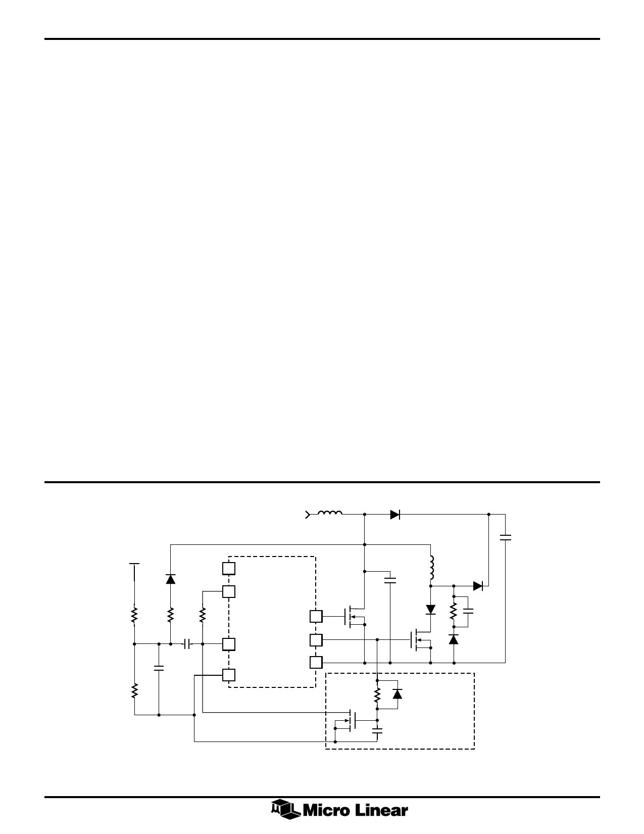
Figure 1 shows a simplified schematic of the output and
control sections of a high power PFC circuit. Figure 2
shows the relationship of various waveforms in the circuit.
Q1 functions as the main switching FET and Q2 provides
the ZVS action. During each cycle, Q2 turns on before
Q1, diverting the current in L1 away from D1 into L2. The
current in L2 increases linearly until at t2 it equals the
current through L1. When these currents are equal, L1
ceases discharging current and is now charged through L2
and Q2. At time t2, the drain voltage of Q1 begins to fall.
The shape of the voltage waveform is sinusoidal due to
the interaction of L2 and the combined parasitic
capacitance of D1 and Q1 (or optional ZVS capacitor
CZVS). At t3, the voltage across Q1 is sufficiently low that
the controller turns Q2 off and Q1 on. Q1 then behaves
as an ordinary PFC switch, storing energy in the boost
inductor L1. The energy stored in L2 is completely
discharged into the boost capacitor via D2 during the Q1
off-time and the value of L2 must be selected for
discontinuous-mode operation.
COMPONENT SELECTION
Q1 Turn-Off
Because the ML4822 uses leading edge modulation, the
PFC MOSFET (Q1) is always turned off at the end of each
oscillator ramp cycle. For proper operation, the internal
ZVS flip-flop must be reset every cycle during the
oscillator discharge time. This is done by automatically
resetting the ZVS comparator a short time after the drain
voltage of the main Q has reached zero (refer to Figure 1
sense circuit). This sense circuit terminates the ZVS on
time by sensing the main Q drain voltage reaching zero. It
is then reset by way of a resistor pull-up to VCC (R6). The
advantage of this circuit is that the ZVS comparator is not
reset at the main Q turn off which occurs at the end of the
clock cycle. This avoids the potential for improper reset of
the internal ZVS flip-flop.
Another concern is the proper operation of the ZVS
comparator during discontinuous mode operation (DCM),
which will occur at the cusps of the rectified AC
waveform and at light loads. Due to the nature of the
voltage seen at the drain of the main boost Q during DCM
operation, the ZVS comparator can be fooled into forcing
the ZVS Q on for the entire period. By adding a circuit
which limits the maximum on time of the ZVS Q, this
problem can be avoided. Q3 in Figure 1 provides this
function.
L1
D1
VREF
13 VREF
ML4822
12 VCC
R3
R5
22k
220
C3
33pF
C4
330pF
R4
51k
R6
PFC OUT 11
22k
7 ZV SENSE ZVS OUT 10
8 GND
PWR GND 9
Q1
R2
Q3
L2
CZVS(OPT)
D2
R1
C2
Q2
MAX ZVS
ON TIME LIMIT
+
C1
C5
Figure 1. Simplified PFC/ZVS Schematic.
6
Share Link: 