CA3079 Ver la hoja de datos (PDF) - Intersil
Número de pieza
componentes Descripción
Fabricante
CA3079 Datasheet PDF : 12 Pages
| |||
Specifications CA3059, CA3079
Electrical Specifications TA = +25oC, For all Types, Unless Otherwise Specified. All voltages are measured with respect to
Terminal 7. For Operating at 120VRMS, 50-60Hz (AC Line Voltage) (Note 1) (Continued)
PARAMETERS
SYMBOL
TEST CONDITIONS
MIN TYP MAX UNITS
SENSITIVITY (Note 3) (Figures 4(a), 11)
Pulse Mode
∆V13
Terminal 12 open
-
6
-
mV
NOTES:
1. The values given in the Electrical Characteristics Chart at 120V also apply for operation at input voltages of 208/230V, and 277V, except
for Pulse Duration. However, the series resistor (RS) must have the indicated value, shown in the chart in the Functional Block Diagram,
for the specified input voltage.
2. Pulse Duration in 50Hz applications is approximately 15% longer than shown in Figure 7(b).
3. Required voltage change at Terminal 13 to either turn OFF the triac when ON or turn ON the triac when OFF.
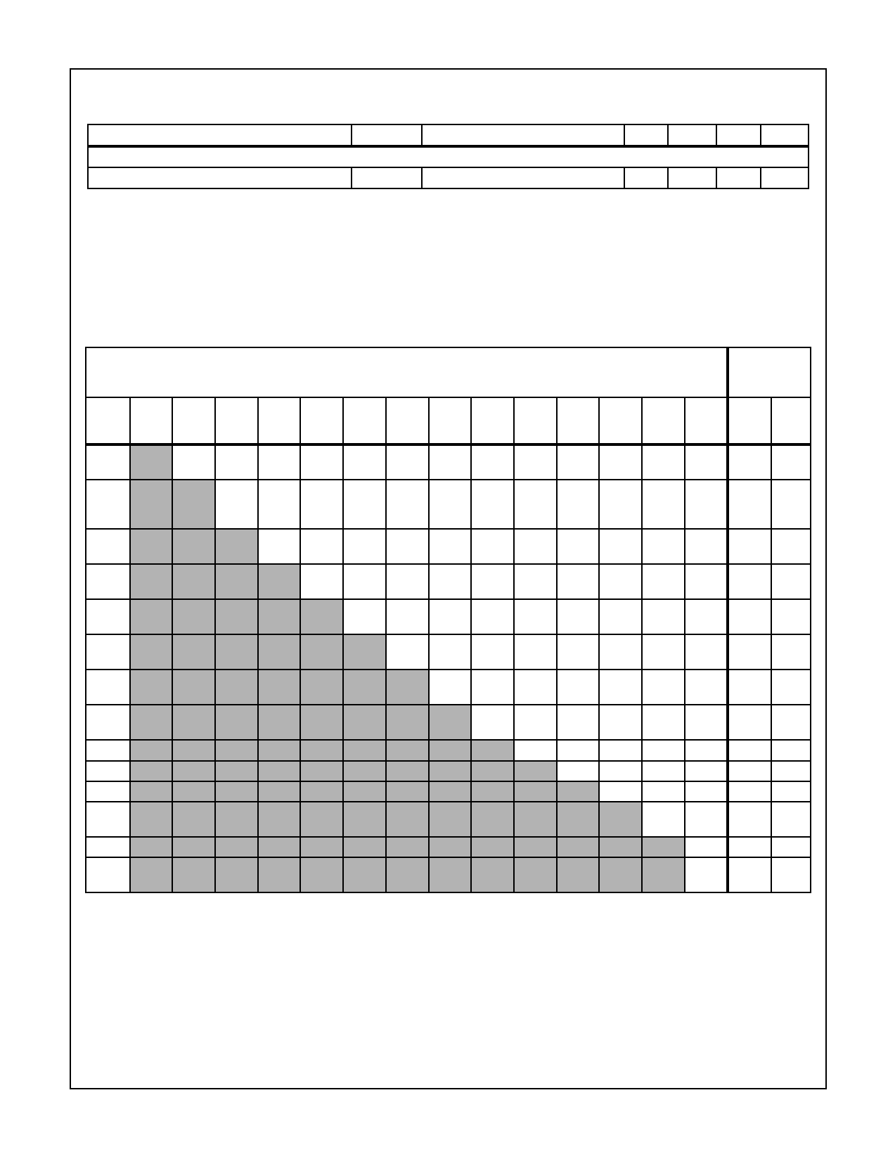
Maximum Voltage Ratings TA = +25oC
MAXIMUM VOLTAGE RATINGS TA = +25oC
MAXIMUM
CURRENT
RATINGS
NOTES
TERM. NOTE 3
NOTE 1 NOTE 3
NOTE 3
2, 3
IIN
IOUT
NO. 1
2
3
4
5
6
7
8
9
10
11
12
13
14 mA mA
1
Note 3
Note 4 Note 4 Note 4 Note 4 15
0
10 Note 4 Note 4 Note 4 Note 4 Note 4 Note 4 Note 4 10 0.1
-2
2
0
0
2
0
0
0
0
0
0 Note 4 0
0
150 10
-15 -15 -14 -14 Note 5 Note 5 -14 -14 -14
-14 -14
-14 -14
3
0 Note 4 Note 4 Note 4 Note 4 Note 4 Note 4 Note 4 Note 4 Note 4 Note 4 Note 4 Note 4
-15
4
Note 4 2 Note 4 Note 4 Note 4 Note 4 Note 4 Note 4 Note 4 Note 4 0.1 150
-10
5
Note 1
Note 4 7 Note 4 Note 4 Note 4 Note 4 Note 4 Note 4 Note 4 50 10
-7
6
Note 3
14 Note 4 Note 4 Note 4 Note 4 Note 4 Note 4 Note 4 Note 4 Note 4
0
7
Note 4 14 Note 4 20 2.5 14
6 Note 4 Note 4
0
0 -2.5 0
-6
8
10 Note 4 Note 4 Note 4 Note 4 Note 4 0.1
2
0
9
Note 4 Note 4 Note 4 Note 4 Note 4 Note 4 Note 4
10
Note 4 Note 4 Note 4 Note 4 Note 4 Note4
11
Note 4 Note 4 Note 4 Note 4 Note4
12
Note 3
Note 4 Note 4 50 50
13
Note 4 Note 4 Note4
14
Note 3
2
2
This chart gives the range of voltages which can be applied to the terminals listed horizontally with respect to the terminals listed vertically.
For example, the voltage range of horizontal Terminal 6 to vertical Terminal 4 is 2V to -10V.
NOTES:
1. Resistance should be inserted between Terminal 5 and external supply or line voltage for limiting current into Terminal 5 to less than
50mA.
2. Resistance should be inserted between Terminal 14 and external supply for limiting current into Terminal 14 to less than 2mA.
3. For the CA3079 indicated terminal is internally connected and, therefore, should not be used.
4. Voltages are not normally applied between these terminals; however, voltages appearing between these terminals are safe, if the spec-
ified voltage limits between all other terminals are not exceeded.
5. For CA3079 (0V to -10V).
6
Share Link: 