RF9678 Ver la hoja de datos (PDF) - RF Micro Devices
Número de pieza
componentes Descripción
Fabricante
RF9678 Datasheet PDF : 16 Pages
| |||
RF9678
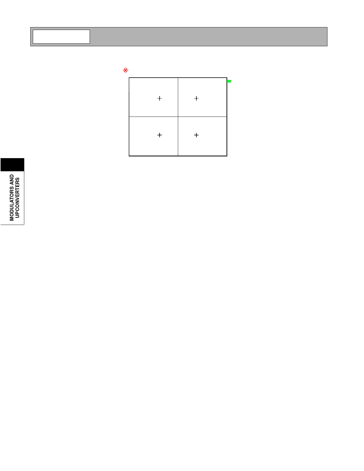
Ref Lvl
0 dBm
1.5
IMAG
T1
CF
380 MHz Meas Signal
SR
3.84 MHz Constellation
Demod
QPSK
A
EXT
Preliminary
5
-1.5
-1.875
Date:
6.FEB.2001 00:38:12
REAL
1.875
Figure 3. DC Offset Error (Carrier Feedthrough)
As is shown above, the EVM performance of a modulator can be correlated to it's carrier and sideband suppression per-
formance.
Unadjusted Performance
A Wideband CDMA signal is a noise-like signal occupying a channel bandwidth of 3.84MHz. When viewed on a spec-
trum analyzer the channel appears as a plateau raised above the noise floor (see Figure 4). In some cases, it is normal
to see a spike over the center of the W-CDMA plateau. This will occur when the absolute power level of the unadjusted
carrier feedthrough is higher than that of the W-CDMA channel level. The cause of this phenomenon can be understood
by examining the relative powers of the carrier signal and the W-CDMA channel power.
For Example, a 1Hz channel with a power of 0dBm has an absolute power level of 0dBm when viewed on a spectrum
analyzer. When that 0 dBm channel power is spread over a 3.84MHz channel, as in W-CDMA, it results in an absolute
channel power level of -65.8 dBm (-10*log (BW)). The absolute channel level displayed on the spectrum analyzer will
increase with the resolution bandwidth setting on the instrument although the integrated channel power will remain con-
stant. A resolution bandwidth (RBW) of 30kHz will increase the displayed power level by 44.7dB (+10*log(RBW)) to -
21.0dBm. With a desired signal output power of +2.0dBm and a carrier suppression of >20dBc, the absolute carrier level
can be as high as -18.0dBm (POUT-Suppression=Carrier Level). This will result in a 3dB carrier spike above the W-
CDMA channel level (see Figure 4). (Note: The relative height of the carrier spike above the W-CDMA channel level is
directly related to the RBW of the spectrum analyzer being used. The example above assumes a 30kHz RBW.)
The following equations may be used to calculate W-CDMA channel and carrier feedthrough levels.
W-CDMA Channel Level=Channel Power (Integrated over BW)-[10*log*(BW)]+[10*log*(RBW)]
Carrier Feedthrough=POUT (Desired Sideband)-Carrier Suppression
The next section describes a procedure that may be used to dramatically reduce carrier feedthrough by tuning or opti-
mizing the modulator input signals.
5-96
Rev A4 010622
Share Link: 