IXDN414 Ver la hoja de datos (PDF) - IXYS CORPORATION
Número de pieza
componentes Descripción
Fabricante
IXDN414 Datasheet PDF : 10 Pages
| |||
IXDN414PI / N414CI / N414CM / N414YI / N414YM
IXDI414PI / I414CI / I414CM / I414YI / I414YM
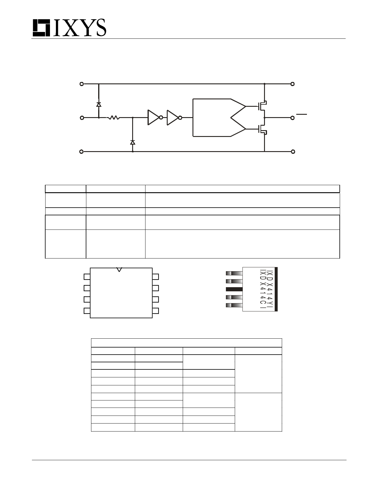
Figure 2 - IXDI414 Inverting 14A Gate Driver Functional Block Diagram
Vcc
Vcc
P
ANTI-CROSS
IN
CONDUCTION
OUT
CIRCUIT *
N
GND
GND
Pin Description And Configuration
SYMBOL
VCC
IN
OUT
GND
FUNCTION
Supply Voltage
Input
Output
Ground
DESCRIPTION
Positive power-supply voltage input. This pin provides power to the
entire chip. The range for this voltage is from 4.5V to 25V.
Input signal-TTL or CMOS compatible.
Driver Output. For application purposes, this pin is connected via an
external resistor to a Gate of a MOSFET/IGBT.
The system ground pin. Internally connected to all circuitry, this pin
provides ground reference for the entire chip. This pin should be
connected to a low noise analog ground plane for optimum
performance.
1 VCC
I
X
2 IN
D
X
3 NC
4
1
4 GND
4
VCC 8
OUT 7
OUT 6
GND 5
8 PIN DIP (PI)
1
Vcc
2
OUT
3
GND
4
IN
5
NC
TO220 (CI, CM)
TO263 (YI, YM)
ORDERING INFORMATION
Part Number Package Type Temp. Range Configuration
IXDN414PI
IXDN414CI
8-Pin PDIP
5-Pin TO-220
-40°C to +85°C
IXDN414CM 5-Pin TO-220 -55°C to +125°C Non Inverting
IXDN414YI 5-Pin TO-263 -40°C to +85°C
IXDN414YM 5-Pin TO-263 -55°C to +125°C
IXDI414PI
IXDI414CI
8-Pin PDIP
5-Pin TO-220
-40°C to +85°C
IXDI414CM 5-Pin TO-220 -55°C to +125°C Inverting
IXDI414YI 5-Pin TO-263 -40°C to +85°C
IXDI414YM 5-Pin TO-263 -55°C to +125°C
NOTE: Mounting or solder tabs on all packages are connected to ground
* Patent Pending
2
Share Link: 