VPX3224E Ver la hoja de datos (PDF) - Micronas
Número de pieza
componentes Descripción
Fabricante
VPX3224E Datasheet PDF : 92 Pages
| |||
VPX 322xE
ADVANCE INFORMATION
2.2. Adaptive Comb Filter (VPX 3226E only)
The 4H adaptive comb filter is used for high-quality lumi-
nance/chrominance separation for PAL or NTSC com-
posite video signals. The comb filter improves the lumi-
nance resolution (bandwidth) and reduces interferences
such as cross-luminance and cross-color. The adaptive
algorithm eliminates most of the mentioned errors with-
out introducing new artifacts or noise.
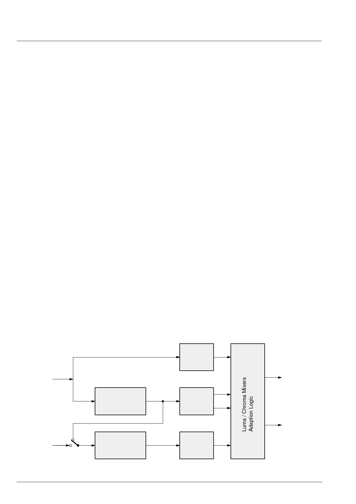
A block diagram of the comb filter is shown in Fig. 2–3.
The filter uses four line delays to process the information
of three video lines. To have a fixed phase relationship
of the color subcarrier in the three channels, the system
clock (20.25 MHz) is fractionally locked to the color sub-
carrier. This allows the processing of all color standards
and substandards using a single crystal frequency.
The CVBS signal in the three channels is filtered at the
subcarrier frequency by a set of bandpass / notch filters.
The output of the three channels is used by the adaption
logic to select the weighting that is used to reconstruct
the luminance/chrominance signal from the 4 bandpass/
notch filter signals. By using soft mixing of the 4 signals,
switching artifacts of the adaption algorithm are com-
pletely suppressed.
The comb filter uses the middle line as reference, there-
fore, the comb filter delay is two lines. If the comb filter
is switched off, the delay lines are used to pass the luma/
chroma signals from the A/D converters to the luma/
chroma outputs. Thus, the processing delay is always
two lines.
In order to obtain the best-suited picture quality, it is pos-
sible for the user to influence the behavior of the adap-
tion algorithm going from moderate combing to strong
combing. The following three parameters may be ad-
justed:
– HDG (horizontal difference gain)
– VDG (vertical difference gain)
– DDR (diagonal dot reducer)
HDG typically defines the comb strength on horizontal
edges. It determines the amount of the remaining cross-
luminance and the sharpness on edges respectively. As
HDG increases, the comb strength, e.g. cross lumi-
nance reduction and sharpness, increases.
VDG typically determines the comb filter behavior on
vertical edges. As VDG increases, the comb strength,
e.g. the amount of hanging dots, decreases.
After selecting the comb filter performance in horizontal
and vertical direction, the diagonal picture performance
may further be optimized by adjusting DDR. As DDR in-
creases, the dot crawl on diagonal colored edges is re-
duced.
To enhance the vertical resolution of the the picture, the
VPX 3226E provides a vertical peaking circuitry. The fil-
ter gain is adjustable between 0 and +6 dB, and a coring
filter suppresses small amplitudes to reduce noise arti-
facts. In relation to the comb filter, this vertical peaking
contributes greatly to an optimal two-dimensional reso-
lution homogeneity.
CVBS Input
2H Delay Line
Bandpass
Filter
Bandpass/
Notch
Filter
Chroma Input
2H Delay Line
Bandpass
Filter
Fig. 2–3: Block diagram of the adaptive comb filter (PAL mode)
10
Luma Output
Chroma Output
Micronas
Share Link: 