L9935(1999) Ver la hoja de datos (PDF) - STMicroelectronics
Número de pieza
componentes Descripción
Fabricante
L9935 Datasheet PDF : 19 Pages
| |||
L9935
Diagnosis of a Short to Ground
Detecting an overload will set an overcurrent error (Error2 = LOW) (bit6). To reset the error flag a new
byte must be written into the interface. (Reset of the error flag takes place at the rising slope of CSN).
Shorted Load
With a shorted load both, the sink- and the source protection or the PWM alone will respond. In either
case there will be no flyback pulse.
Diagnosis of a Shorted Load
Shorting the load two events may take place:
- overload (of the high side transistor) while low side transistor overcurrent is detected will set the
following combinations:
bit6 = LOW
bit7 = HIGH
- overload is marginal. So the low side driver may turn off before overload is detected. This leads to the
combination bit6 = HIGH and bit7 = LOW.
Open Load
An open load will not lead to any flyback pulses. Error detection will take advantage of the flyback pulse.
Missing the flyback pulse after reversing the polarity of a motor winding bit7 will become LOW.
Open load will not be tested in the low current mode (current bits HL) to avoid the risk of instable diagno-
sis at low flayback currents. Open load immediately after reset or power down may on random be de-
tected in the low current mode too. This diagnosis however will not persist longer than 8 changes of po-
larity. We strongly suggest to test open load at a high current mode (combination LH or LL).
Overtemperature Prealarm
Typically 20K before thermal shut down takes place an overtemperature prealarm (bit7 and bit6 low)
takes place. Typically overtemperature prealarm temperature is between 150°C and 160°C.
Application hints using a high resistive stepper motor
The L9935 was originally targeted on stepper chopping stepper motor application with typical resis-
tances of 8..12W. Using motors with higher resistance will work too but diagnosis behaviour will slightly
change. This paragraph shows the details that should be taken in account using diagnosis for high resis-
tive motors.
Startup behaviour:
The device has simple digital filter to avoid triggering diagnosis at a single event that could be random
noise. This digital filter needs 4 chopping pulses to settle. Using a high resistive motor this chopping
does not take place. Instead the digital filter samples each time a polarty change takes place. So the first
three response telegrams after reset may show an ’open load’ error.
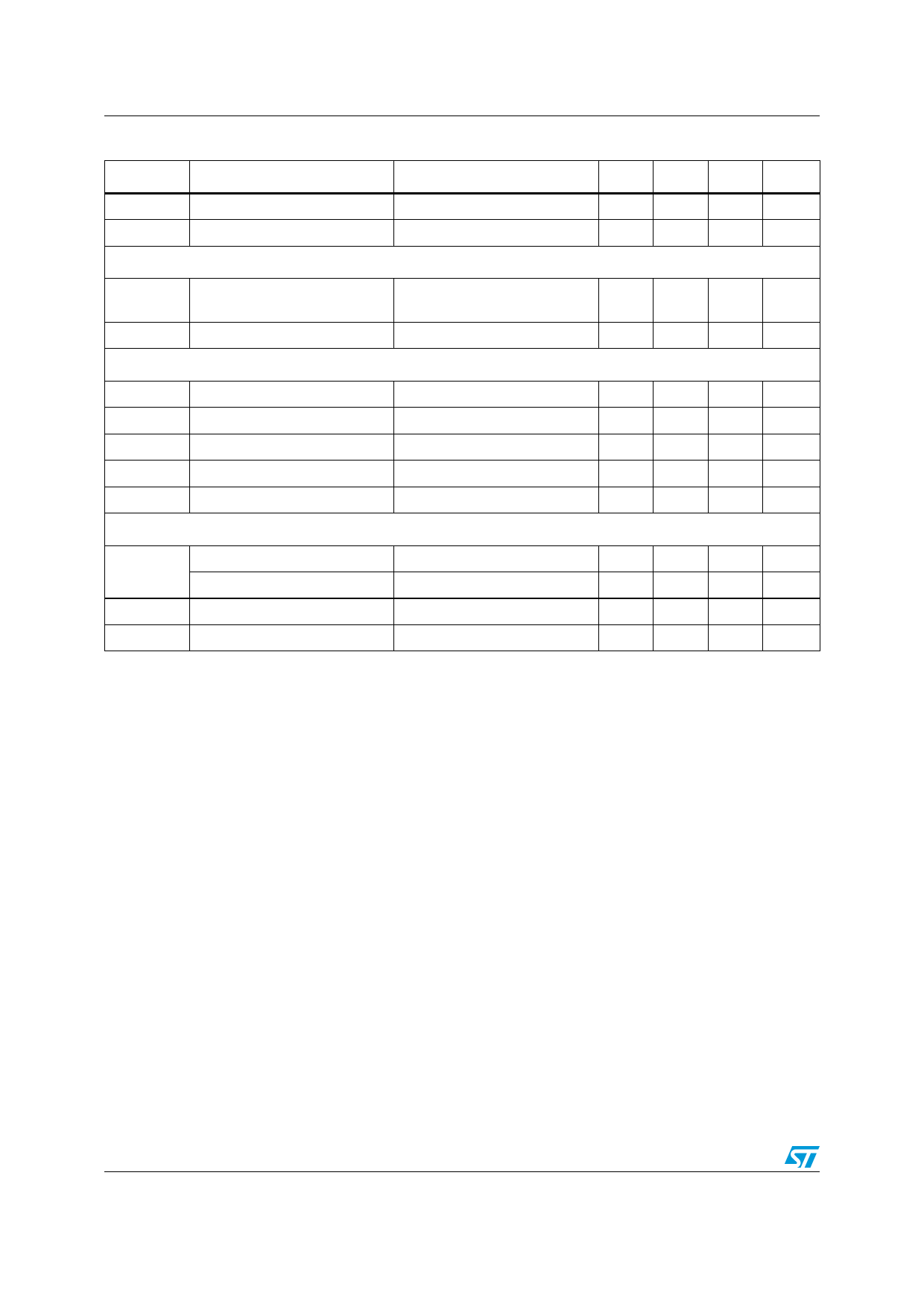
Inpu t data
Standby
1st telegram (550mA or 900mA)
Reverse phase (550mA or 900mA)
Reverse phase (550mA or 900mA)
Any data
Any data
High resistive motor (error bits)
HH
XH
XH
XH
HH
Low resistive motor (error bits)
HH
HH
HH
HH
HH
H means check for HIGH at the error bits.
X means don’t care because filter is not yet settled.
10/19
Share Link: 