BR211SM-140 Ver la hoja de datos (PDF) - Philips Electronics
Número de pieza
componentes Descripción
Fabricante
BR211SM-140 Datasheet PDF : 6 Pages
| |||
Philips Semiconductors
Breakover diodes
Preliminary specification
BR211SM series
STATIC CHARACTERISTICS
Tj = 25 ˚C unless otherwise stated
SYMBOL PARAMETER
VTM1
V(BR)
V(BO)
On-state voltage
Avalanche voltage (min)
Breakover voltage (max)
SIH(2br)
Temperature coefficient of V(BR)
Holding current
IISD34
Switching current
Off-state current
CONDITIONS
ITM = 2 A
I(BR) = 10mA
I ≤ IS, tp = 100 µs
BR211SM-140
BR211SM-160
BR211SM-180
BR211SM-200
BR211SM-220
BR211SM-240
BR211SM-260
BR211SM-280
Tj = 25˚C
Tj = 70˚C
tp = 100 µs
VD = 85% V(BR)min, Tj = 70˚C
DYNAMIC CHARACTERISTICS
Tj = 25 ˚C unless otherwise stated
SYMBOL PARAMETER
dVD/dt
Cj
Linear rate of rise of off-state
voltage that will not trigger any
device
Off-state capacitance
CONDITIONS
V(DM) = 85% V(BR)min; Tj = 70 ˚C
VD = 0 V; f = 1 kHz to 1 MHz
MIN. TYP. MAX. UNIT
-
-
2.5 V
123 140 157 V
140 160 180 V
158 180 202 V
176 200 224 V
193 220 247 V
211 240 269 V
228 260 292 V
246 280 314 V
- +0.1 - %/K
150 -
-
mA
100 -
-
mA
10 200 1000 mA
-
-
10 µA
MIN. TYP. MAX. UNIT
-
- 2000 V/µs
-
- 100 pF
current VT
IT
IH
ID
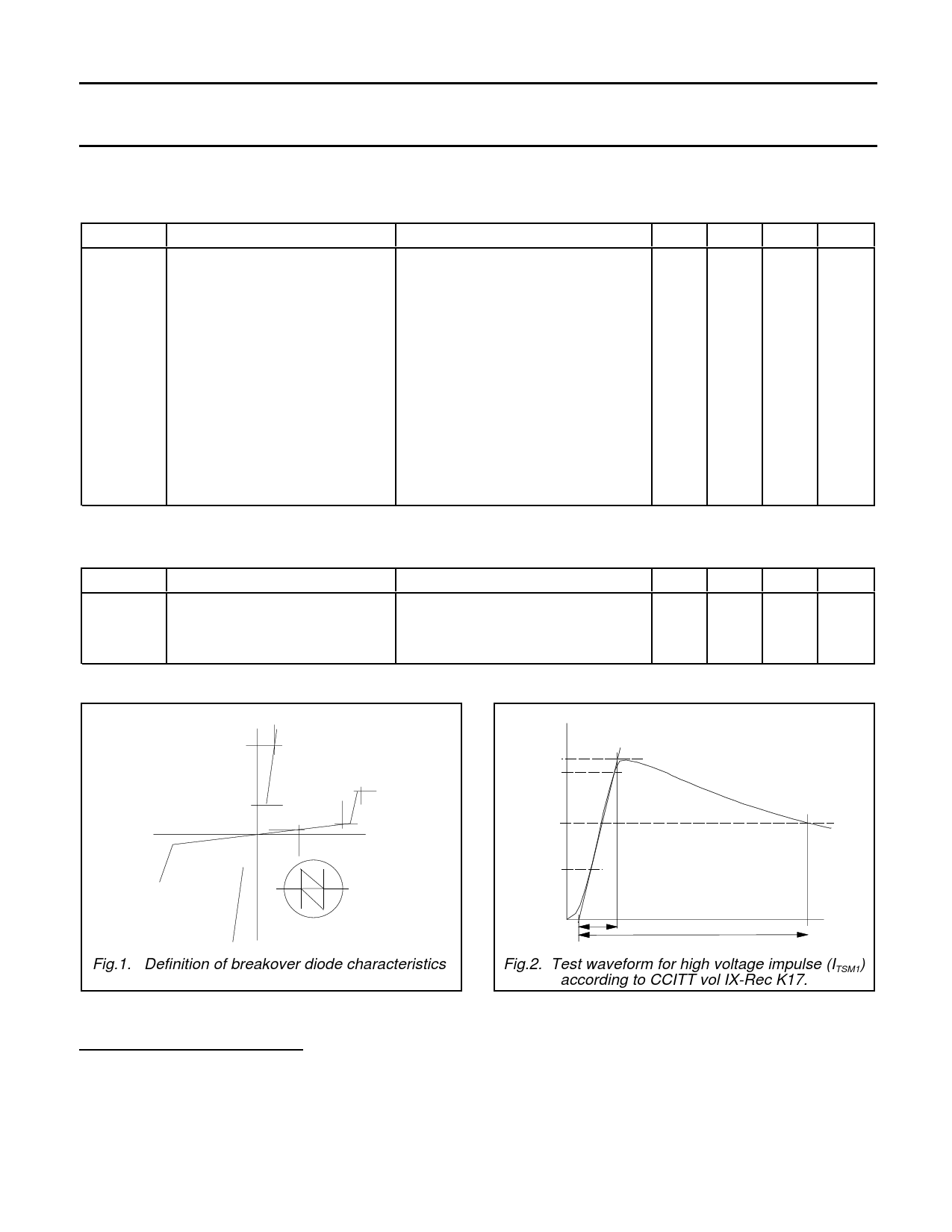
V(BR)
I(BR)
IS
V(BO)
VD voltage
Symbol
Symmetric BOD
Fig.1. Definition of breakover diode characteristics.
current
100%
90%
ITSM
50%
30%
0
time
10us
700us
Fig.2. Test waveform for high voltage impulse (ITSM1)
according to CCITT vol IX-Rec K17.
1 Measured under pulsed conditions to avoid excessive dissipation
2 The minimum current at which the diode will remain in the on-state
3 The avalanche current required to switch the diode to the on-state
4 Measured at maximum recommended continuous voltage. Relative humidity < 65%.
August 1996
2
Rev 1.100
Share Link: 