LS7237 Ver la hoja de datos (PDF) - LSI Corporation
Número de pieza
componentes Descripción
Fabricante
LS7237 Datasheet PDF : 4 Pages
| |||
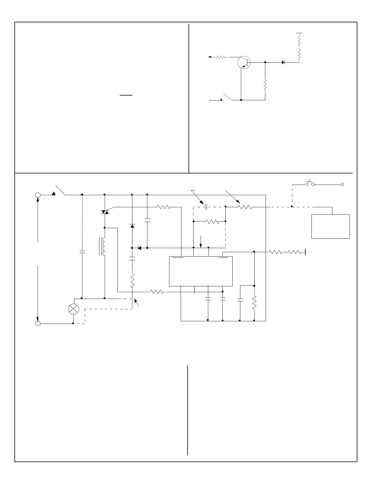
APPLICATION EXAMPLES:
A typical implementation of a lamp dimmer circuit is shown in Fig. 5.
Here the brightness of the lamp is set by touching the Touch Plate .
The functions of different components are as follows:
• The 15V DC supply for the chip is provided by Z, D1, R1, C2, C5.
• R2 and C4 generate the filtered signal for the SYNC input for syn-
chronizing the internal PLL with the line frequency.
• R3 and C7 act as filter circuit for the electronic extension. If exten-
sions are not used, the EXT input (Pin 6) should be tied to VDD
(Pin 7).
• R4, R5, R6 set up the sensitivity of the SENS input. C6 provides
noise filtering.
• C3 is the filter capacitor for the internal PLL.
• R8 provides current limiting and isolation between the chip output
and the triac gate.
• C1 and L are RF filter circuits.
In the case of momentary power failure, the circuit state remains un-
changed for a period up to 1 sec. For longer power interruptions, the
output is shut off.
EXTN
P
2KΩ ,1/4W
MPS8599
TOUCH PLATE
*R
*R
IN914
200K Ω ,1/4W
*R = 2MΩ , 1/4W for 115VAC
*R = 3.6MΩ , 1/4W for 220VAC
FIGURE 6. ELECTRONIC EXTENSION
EXTENSIONS:
All switching and dimming functions can also be implemented by
utilizing the EXT input. This can be done by either a mechanical
switch or the electronic switch in conjunction with a Touch Plate
as shown in Figure 6. When the plate is touched, a logic high lev-
el is generated at the EXT input of the IC for both half-cycles of
the line frequency. (See Figure 5)
P
115VAC
OR
C1
220VAC
LOAD
FIGURE 5. A Typical Lamp Dimmer
SEE NOTE 2
G
MT1
MT2 T
R8
+
C5
Z-
C7
R3
SEE NOTE 4
L
D1
87 6 5
C2
TRIG VDD EXT SENS
LS7237
R1
VSS MODE CAP SYNC
R2
1 23 4
A
B
SEE NOTE 3
C3 C4
P
R7
EXTN
ELECTRONIC
EXTENSION
(FIG. 6)
R6 R5
TOUCH
PLATE
C6 R4
N
NOTES:
1) All circuits connected by broken lines are optional.
2) C7 is used only with electronic extension and R7 is used only with mechanical switch
3) Use Connection A when Neutral is not available. Use Connection B when Neutral is available.
4) Connection between Pin 6 and Pin 7 should be broken when EXT is used.
C1 = 0.15µF,200V
(1) C2 = 0.33µF,200V
C3 = 0.047µF,25V
C4 = 470pF,25V
C5 = 47µF,25V
C6 = 680pF,25V
C7 = 0.1µF,25V
(2) R1 = 270Ω,1W
R2 = 1.5MΩ,1/4W
R3 = 1.5MΩ,1/4W
115V
R4 = 1MΩ to 5MΩ,1/4W
(Select for sensitivity)
R5, R6 = 2.7MΩ,1/4W
R7 = 150KΩ,1/4W
R8 = 100Ω,1/4W
D1 = IN4148
Z = 15V,1W (Zener)
T = Q4006L4 Triac (Typical)
L = 100µH (RFI Filter)
(1) For Connection A. Use 0.22µF for Connection B.
(2) For Connection A, Modes 1 and 2. Use 1/4W for Mode 0
and Connection B, all Modes.
7237-041597-4
C1 = 0.15µF,400V
(3) C2 = 0.22µF,400V
C3 = 0.047µF,25V
C4 = 470pF,25V
C5 = 47µF,25V
C6 = 680pF,25V
C7 = 0.1µF,25V
(4) R1 = 1KΩ, 2W
R2 = 1.5MΩ,1/4W
R3 = 1.5MΩ,1/4W
220V R4 = 1MΩ to 5MΩ,1/4W
(Select for sensitivity)
R5, R6 = 4.7MΩ,1/4W
R7 = 150KΩ,1/4W
R8 = 100Ω,1/4W
D1 = 1N4148
Z = 15V,1W (Zener)
T = Q5004L4 Triac (Typical)
L = 200µH (RFI Filter)
(3) For Connection A. Use 0.1µF for Connection B.
(4) For Connection A, Modes 1 and 2. Use 1/4W for Mode 0
and Connection B, all Modes.
Share Link: 