74LV4799 Ver la hoja de datos (PDF) - Philips Electronics
Número de pieza
componentes Descripción
Fabricante
74LV4799 Datasheet PDF : 18 Pages
| |||
Philips Semiconductors
Timer for NiCd and NiMH chargers
Product specification
74LV4799
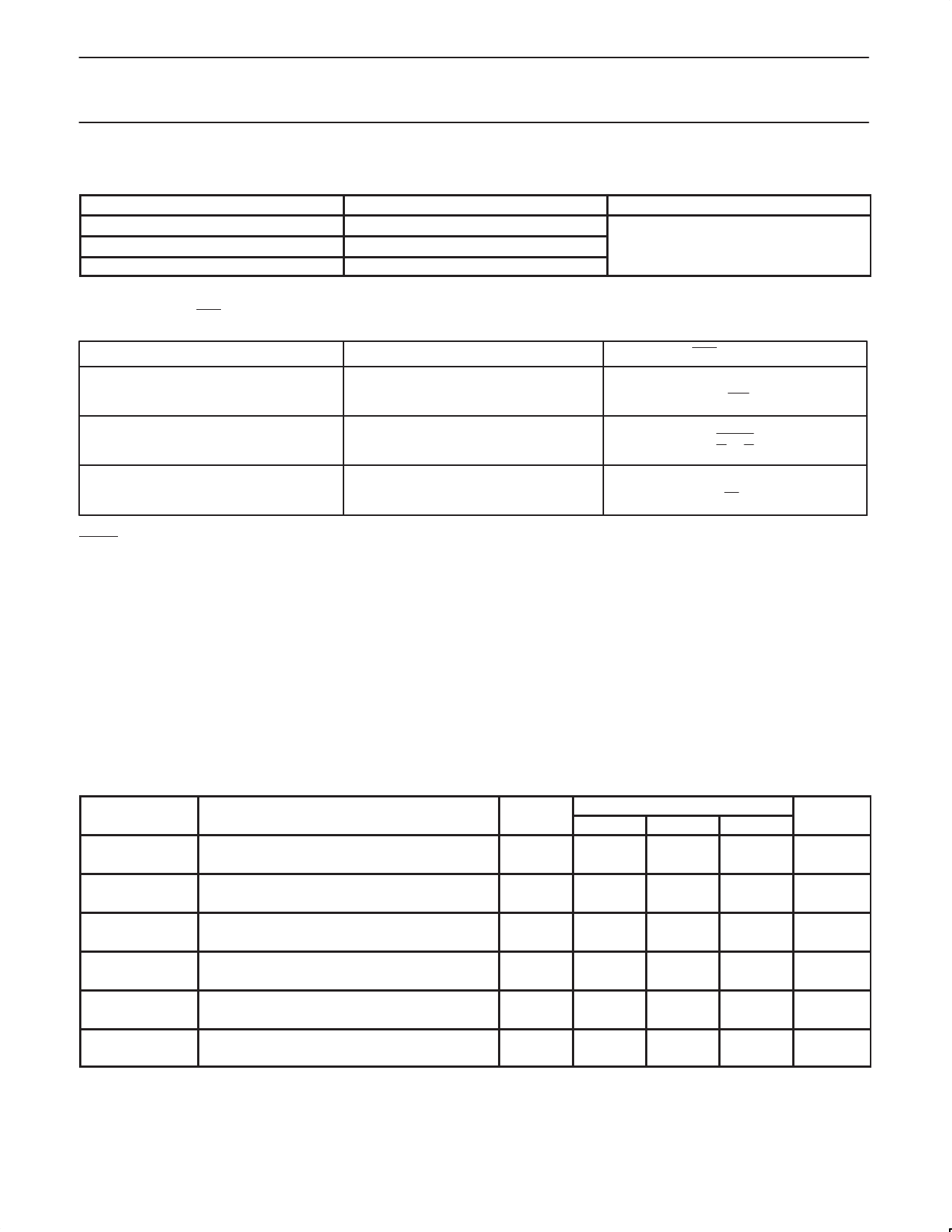
Charge discharge times
PARAMETER
Charge time
Discharge time
Self-discharge time
TIME RANGE
4 hours to 16 hours
15 minutes to to 4.7 hours
50 days to 100 days
LED frequency
The frequency of the LED output (pin1) is determined by the oscillator frequency.
Three modes of operation, each with its own frequency, are possible.
Mode
SEL
Charge
H or open
Trickle charge
L
Alarm
H
CONDITIONS
Components ranges are within the values
given in Section “External components range”
LED frequency
fC
256
1
8
fC
)
6
fS
fD
32
MOLLI pulse duration
The MOLLI output gives an output signal of four periods with a 50%
duty cycle. The duration of one period is determined by: 16/fs
Timing accuracy.
The timing accuracy depends on the accuracy of the on–chip
oscillator and on the external R and C components. The inaccuracy
of the on–chip oscillator is specified as maximum +/–7%. In most
cases the actual inaccuracy will be significantly lower. This depends
on the supply voltage as well as the value of the external
components.
Influence of Resistor value.
Low resistor values cause some spread because the RC
combination is biased by a 3–State push–pull output. The spread of
SPREAD-CAUSING FACTORS
SYMBOL
PARAMETER
Voff
tP
RON
RON
RON
RON
Offset voltage
Propagation delay
P-channel resistance RC, RD outputs
N-channel resistance RC, RD outputs
P-channel resistance RS output
N-channel resistance RS output
the Ron of the push–pull stage will contribute to the frequency
spread. When high–value resistors are used, any possible output
leakage of the not–selected 3–State outputs will cause a frequency
deviation. For these reasons, the resistor values must be within the
specified ranges.
Influence of supply voltage
The trip levels of the oscillator are fixed at 20% and 80% of Vcc. At
higher supply voltages the spread of the trip levels decreases in
greater proportion because the offset voltage remains constant, and
the propagation delay decreases. Furthermore, the Ron values of
the push–pull driving stage decrease at higher voltages.
VCC
(V)
Tamb (°C)
MIN
TYP
MAX
UNIT
1.0
7
mV
6.0
7
mV
1.0
22
ms
6.0
5.5
ms
1.0
170
W
6.0
25
W
1.0
250
W
6.0
35
W
1.0
1300
W
6.0
180
W
1.0
1300
W
6.0
180
W
1998 Apr 20
10
Share Link: 