TEA1610T Ver la hoja de datos (PDF) - Philips Electronics
Número de pieza
componentes Descripción
Fabricante
TEA1610T Datasheet PDF : 20 Pages
| |||
Philips Semiconductors
Zero-voltage-switching
resonant converter controller
Product specification
TEA1610P; TEA1610T
Dead time resistor Rdt (see Fig.10)
The dead time resistor Rdt is connected between the 3 V
reference pin (VREF) and the IFS current input pin. The
voltage on the IFS pin is kept constant at a temperature
independant value of 0.6 V. The current that flows into the
IFS pin is determined by the value of resistor Rdt and the
2.4 V voltage drop across this resistor. The IFS input
current equals the discharge current of capacitor Cf and
determines the falling slope of the oscillator.
The falling slope time is used to create a dead time (tdt)
between two successive switching actions of the
half-bridge switches:
IIFS = 2---R-.--4--d---Vt--
tdt = C-----f---×I--I--F-∆--S--V----C---f
tIFS = tdt
Minimum frequency resistor (see Fig.10)
The Rf(min) resistor is connected between the VREF pin (3 V
reference voltage) and the IRS current input (held at a
temperature independant voltage level of 0.6 V). The
charge current of the capacitor Cf is twice the current
flowing into the IRS pin.
The Rf(min) resistor has a voltage drop of 2.4 V and its
resistance defines the minimum charge current (rising
slope) of the Cf capacitor if the control current is zero. The
minimum frequency is defined by this minimum charge
current (IIRS1) and the discharge current:
IIRS1 = -R-2---f-.-(4--m---V-i-n---)
tIRS1 = -C-2---f--×-×----I-∆-I-R--V-S---C-1--f
fmin = -t-d---t---+---1--t--I-R---S---1-
Maximum frequency resistor
The output voltage is regulated by changing the frequency
of the half-bridge converter. The maximum frequency is
determined by the R∆f resistor which is connected between
the error amplifier output VCO and the oscillator current
input pin IRS. The current that flows through the R∆f
resistor (IIRS2) is added to the current flowing through the
Rf(min) resistor. As a result, the charge current ICF
increases and the oscillation frequency increases. As the
falling slope of the oscillator is constant, the relationship
between the output frequency and the charge current is
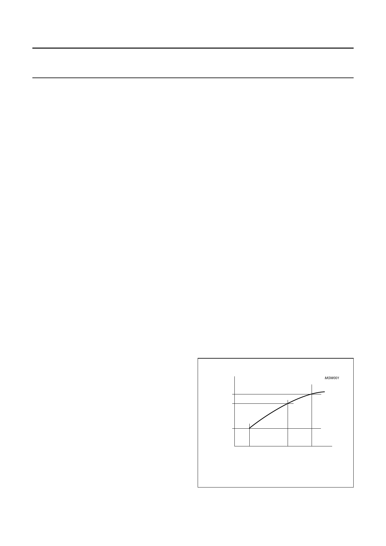
not a linear function (see Figs 7 and 9):
IIRS2 = V-----V---C--R--O---∆--–--f--0----.-6--
tIRS2 = -I-I--CR----S-f--1×----+-∆----IV--I-R--C--S-f--2- × 2
The maximum output voltage of the error amplifier and the
value of R∆f determine the maximum frequency:
IIRS2(max) = V-----V---C----O----(-Rm-----a∆--x-f--)---–----0----.--6-
tIRS(min) = I--I--R----S--C-1---f-+--×---I--I∆-R---V-S---C2---(-fm----a---x--) × 2
fmax = T----1o---s--c-
Tosc = tIRS(min) + tIFS
Bridge frequency accuracy is optimum in the low
frequency region. At higher frequencies both the dead time
and the oscillator frequency show a decay.
The frequency of the oscillator depends on the value of
capacitor Cf, the peak-to-peak voltage swing VCf and the
charge and discharge currents. However, at higher
frequencies the accuracy decreases due to delays in the
circuit.
handbook, halffpoasgce
f osc(max)
f osc(start)
MGW001
f osc(min)
0
I IRS
Fig.7 Frequency range.
2001 Apr 25
7
Share Link: 