PST620 Ver la hoja de datos (PDF) - Mitsumi
Número de pieza
componentes Descripción
Fabricante
PST620 Datasheet PDF : 6 Pages
| |||
MITSUMI
System Reset (with battery back-up) PST620, 621
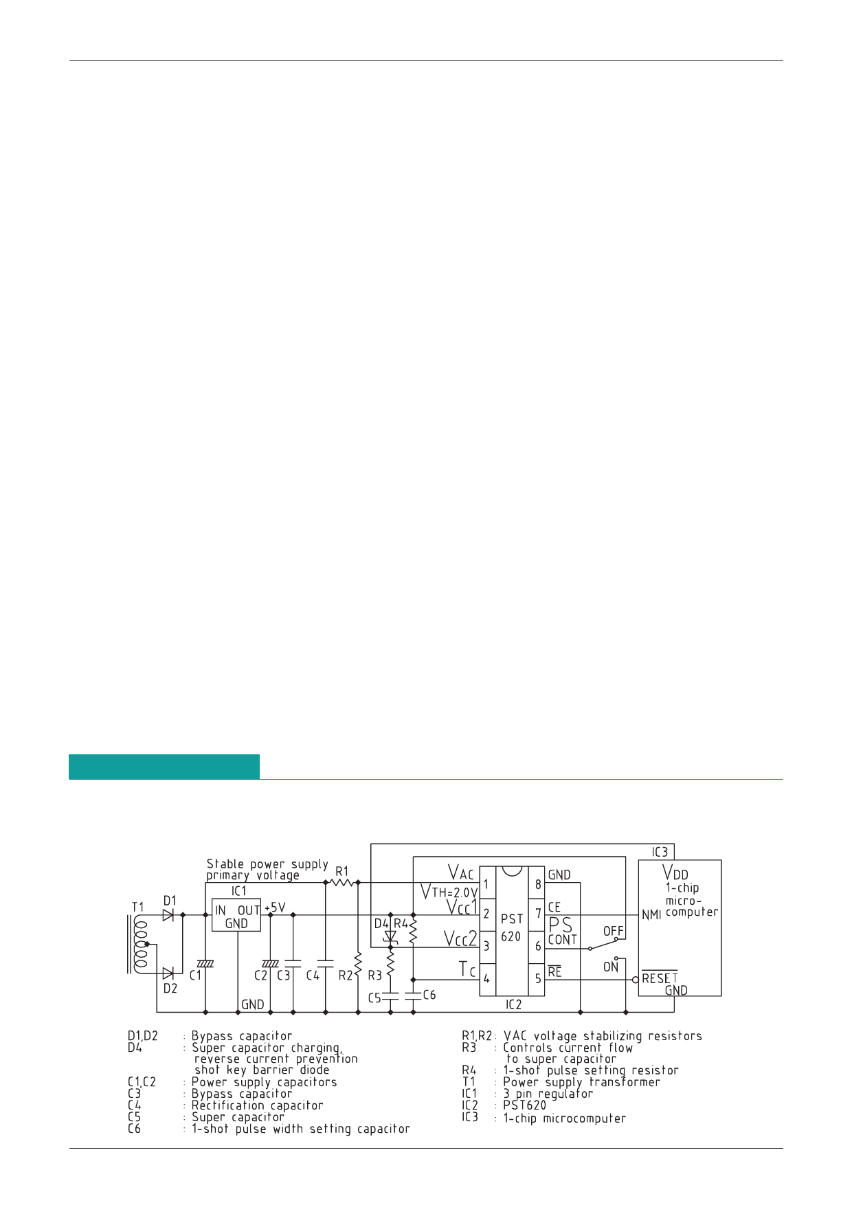
1. Connection
1. +5V power supply to VCC1 (Pin 2).
2. Connect back-up capacitor to VCC2 (Pin 3).
3. Connect a diode between VCC1 (Pin 2) and VCC2 (Pin 3).
4. Connect pulse width setting resistor and capacitor to PC (Pin 4) when using pulse shaver.
5. RE output (Pin 5) is reset signal output and is output when VCC is less than 2.15V.
6. When using pulse shaver, PSCONT (Pin 6) is high level.
7. CE output (Pin 7) is for chip enable signal and goes low when power outage is detected.
2. Theory of Operation
1. When +5V power is supplied normally, it is charged to the back-up capacitor via a diode.
2. The back-up capacitor starts back-up if +5V power supply voltage drops for some reason and
--------------------------
VCC1 goes below 4.2V, and at the same time the CE signal switches the 1-chip microcomputer to
standby mode, so that it operates on low current consumption.
3. When +5V power supply recovers and goes over 4.2V, an RE output signal of a certain width is
output, and this signal resets the 1-chip microcomputer. At the same time normal mode starts and
the time until crystal oscillator output stabilizes is reset.
4. If +5V power supply does not recover, and back-up capacitor voltage goes below 2.15V, reset is
carried out by the RE output signal to prevent the microcomputer from running wild.
3. Setting AC power supply power outage detection
1. Theory of operation for detecting AC voltage
AC voltage is rectified and smoothed by the capacitor. This voltage is divided and set at VAC input
detection voltage, +2V. At this time the smoothing capacitor and dividing resistor time constants
are used to set AC voltage missing waveform.
2. VAC voltage setting (R1, R2)
Set resistor ratio at the midpoint between R1 and R2 so that the voltage to be detected is +2V.
Impressed AC voltage
There is are no limitations on AC voltage as it is divided by R1 and R2 and applied to PST620.
3. Setting time constants to detect AC voltage (C4, R1+R2)
For impressed AC voltage of 5Vrms, and C4 and R1+R2 time constant of 60mS, set so that AC
voltage detects power outage when approximately 2 waveforms are missed. The time constants
can be set to detect missing AC waveforms.
Application Circuits
VAC input : Stable power supply primary voltage detection
Share Link: 