NE56625-20 Ver la hoja de datos (PDF) - Philips Electronics
Número de pieza
componentes Descripción
Fabricante
NE56625-20 Datasheet PDF : 15 Pages
| |||
Philips Semiconductors
System reset with Watchdog timer
Product data
NE56625-20
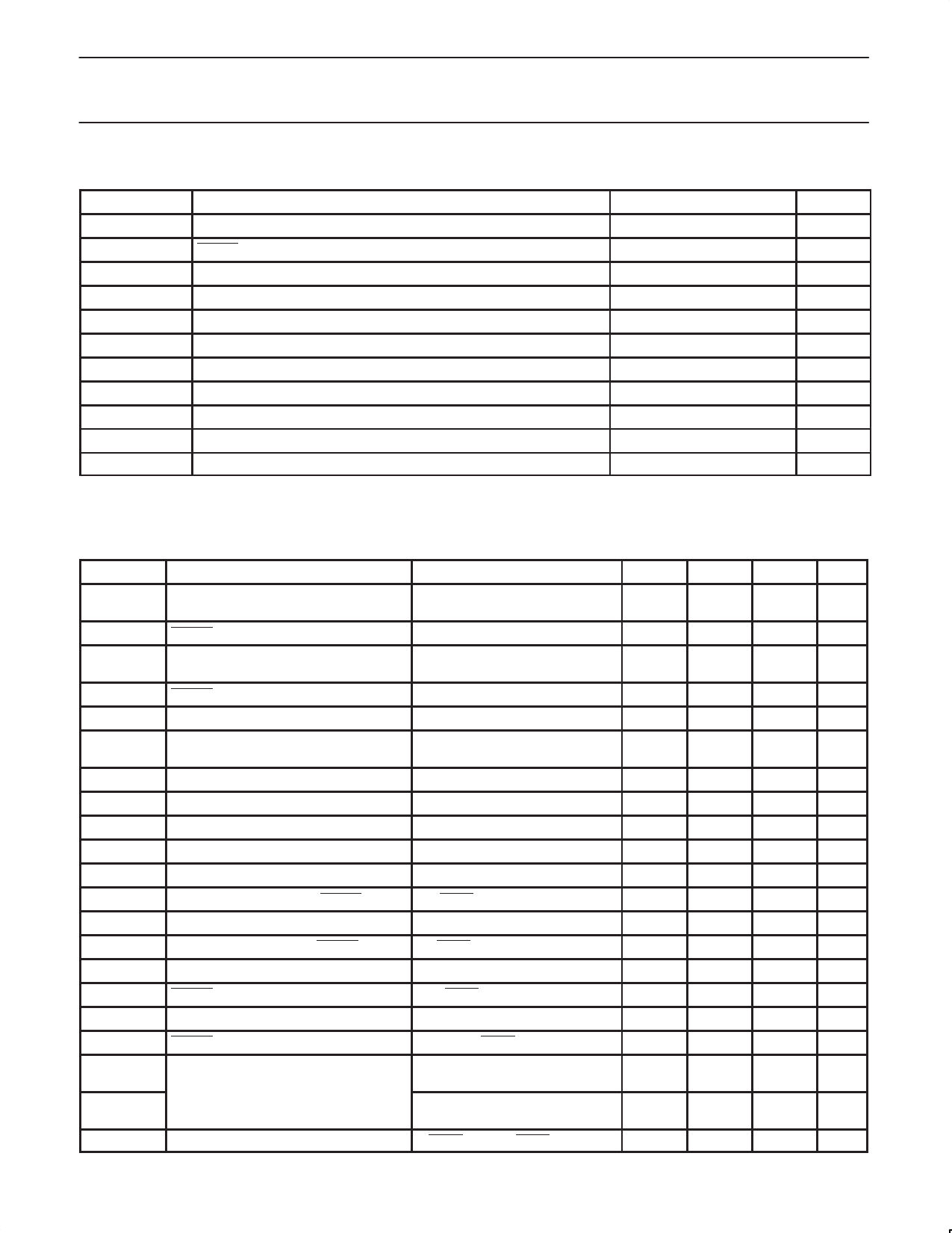
RECOMMENDED OPERATING CONDITIONS
SYMBOL
PARAMETER
VCC
IOLR
IOLC
VCKH
VCKL
tWD
tr(CLK), tf(CLK)
tr(VCC)
tf(VCC)
Tamb
CT
Power supply voltage
RESET sink current
BC sink current
HIGH-level clock input voltage
LOW-level clock input voltage
Clock monitoring time
Clock rise and fall times
Power supply voltage rise time
Power supply voltage fall time
Operating ambient temperature
TC capacitance
RATING
1.9 to 6.5
0 to 500
0 to 5.0
< 1.0
< 0.2
1 to 10,000
< 100
< 100
< 50
–20 to +70
0.0022 to 2.2
UNIT
V
µA
mA
V
V
ms
µs
µs
µs
°C
µF
DC ELECTRICAL CHARACTERISTICS
Tamb = 25 °C, VCC = 2.6 V, unless otherwise specified.
SYMBOL
PARAMETER
ICC
Supply current during Watchdog timer
operation
VSLR
∆VSR/∆Tamb
RESET detection threshold
Temperature coefficient of reset detection
voltage
VhysR
VSLB
∆VSB/∆Tamb
RESET threshold hysteresis
Battery detection voltage
Temperature coefficient of battery
detection voltage
VhysB
∆VSL
VTH
IIH
IIL
VOHR
VOHB
VOLR
VOLB
IOLR
IOLB
IOHR
ICT1
Battery hysteresis voltage
Detection voltage difference
CLK input threshold
HIGH-level CLK input current
LOW-level CLK input current
HIGH-level output voltage, RESET
HIGH-level output voltage, BC
LOW-level output voltage, RESET
LOW-level output voltage, BC
RESET output sink current
Battery Check output sink current
RESET output source current
CT charge current
ICT2
VCCL
Supply voltage to assert reset operation
CONDITIONS
no load
VCC = falling; RCT: GND; VS = open
–20 °C ≤ Tamb ≤ 70 °C
VCC = falling; RCT: GND; VS = open
VCC = falling; RLB = 10 kΩ
VCC = falling; RLB = 10 kΩ
∆VSL = VSLB – VSLR
VCLK = 2.6 V
VCLK = 0 V
IRESET = –1.0 µA; VS = open
RLB = 10 kΩ
IRESET = 500 µA; VCC = 1.8 V
IBC = 5 mA; VCC = 1.8 V
VRESET = 0.5 V; VCC = 1.8 V
VBC = 0.5 V; VCC = 1.8 V
VRESET = 2.0 V
VCT = 0.5 V;
during Watchdog operation
VCT = 0.5 V;
during power-on reset operation
VRESET = 0.4 V; IRESET = 0.05 mA
MIN.
–
1.94
–
25
2.13
–
25
175
0.8
–
–15
2.0
2.0
–
–
500
5
2
–0.3
–0.3
–
TYP.
0.7
2.0
±0.01
50
2.20
±0.01
50
200
1.2
0
–6
2.2
2.2
0.3
0.3
700
7
4
–0.15
–0.15
0.8
MAX.
1.0
UNIT
mA
2.06
±0.05
V
%/°C
100
2.27
±0.05
mV
V
%/°C
100
mV
225
mV
2.0
V
1
µA
–2
µA
–
V
–
V
0.5
V
0.5
V
–
µA
–
mA
–
µA
–0.075 µA
–0.075 µA
1.0
V
2003 Oct 15
4
Share Link: 