ST3917B Ver la hoja de datos (PDF) - STMicroelectronics
Número de pieza
componentes Descripción
Fabricante
ST3917B Datasheet PDF : 16 Pages
| |||
ST3917A - ST3917B
DEVICE OPERATION (continued)
Led Indicator / Tone Mode Indication
When the MU/MFI (Pin 24) is connected to any row
of the keypad input, the LED connected to Pin 15
(LED) becomes a Tone mode indicator.
The LED indicator is used in the following conditions :
- At Tone mode, LED will light up at off-hook. The
LED will turn off only when the telephone goes
on-hook.
Example : Tone mode
OFF-HOOK (LED turns on) <TONE> D1, D2, D3
ON-HOOK (LED turns off)
OFF-HOOK (LED turns on) <TONE> LND
ON-HOOK (LED turns off)
- At Pulse mode after off-hook, LED is off during
pulse dialing. When dialing is followed by the ”*”
or ”TONE” softswitch key depressed, the LED will
light up immediately at the softswitch after pulse
dialing is completed to indicate the signalling
mode change from pulse to tone.
After returning to on-hook and back to off-hook,
the device will be in pulse mode and then LED is
turned off. Redialing from LND memory buffer will
repeat the softswitch, i.e. mixed mode redialing,
the LED will light up to indicate the switch to tone
mode or tone dialing. The LED will turn off only
when the telephone goes on-hook or is reset by
the Flash key
Examples : Pulse mode
a) OFF-HOOK (LED is off) <Pulse> D1, D2
(LED remains off),”*” <Tone> (LED turns on),
D3, D4
ON-HOOK or Flash (LED turns off)
b) OFF-HOOK (LED is off) <Pulse> LND
<Pulse> D1, D2 (LED remains off), ”*” <Tone>
(LED turns on) D3, D4,
ON-HOOK or Flash (LED turns off)
- At Pulse mode, after off-hook, LED is off during
pulse dialing. When switching the Tone/Pulse me-
chanical switch to Tone mode, LED will turn on.
Example : Pulse mode
OFF-HOOK (LED is off) <Pulse> D1, D2 Switch
”Tone/Pulse” mechanical switch to Tone mode
(LED turns on) <Tone> D3, D4,
ON-HOOK (LED turns off)
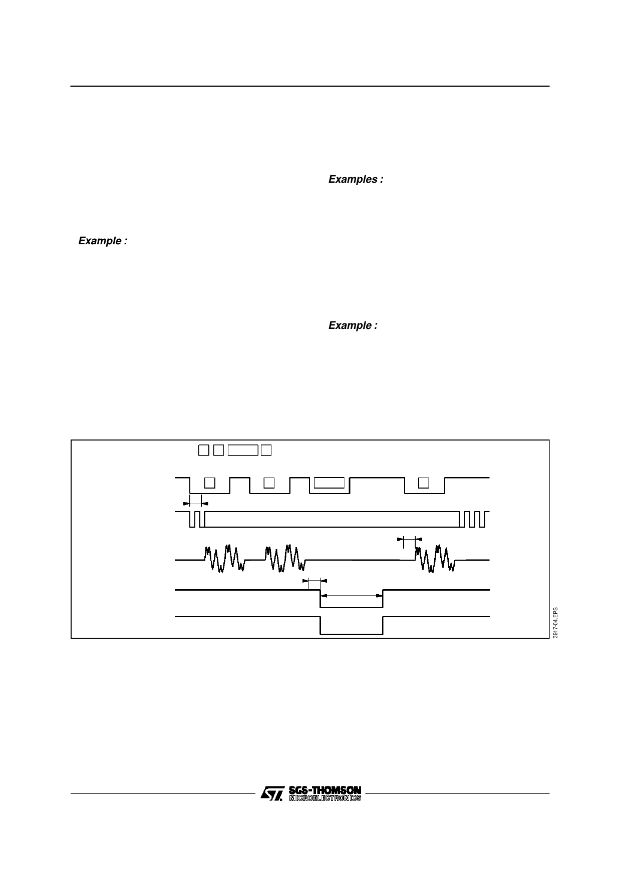
The function of the LED for Tone mode indicator is
described in the timing waveform in Figures 2, 3, 4
and 5.
Figure 2 : Tone Mode Timing with Lighted Dial LED (Pin 24 to VDD or GND)
* Dial Se que nc e 1
FLAS H 3
ENTE R
ENTER
Keybo ard
1
Inp ut
*
3
Keybo ard
Scan
E NTER
F LAS H
KE YBOARD S CAN
DTMF
Outpu t
(P in 17)
P ULS E
Outpu t
3
Tflas h
3 : Debounce Time
E NTE R
3
3
LE D
ON
OFF
ON
9/16
Share Link: 