BTS650PE3180A Ver la hoja de datos (PDF) - Infineon Technologies
Número de pieza
componentes Descripción
Fabricante
BTS650PE3180A Datasheet PDF : 16 Pages
| |||
Data Sheet BTS650P
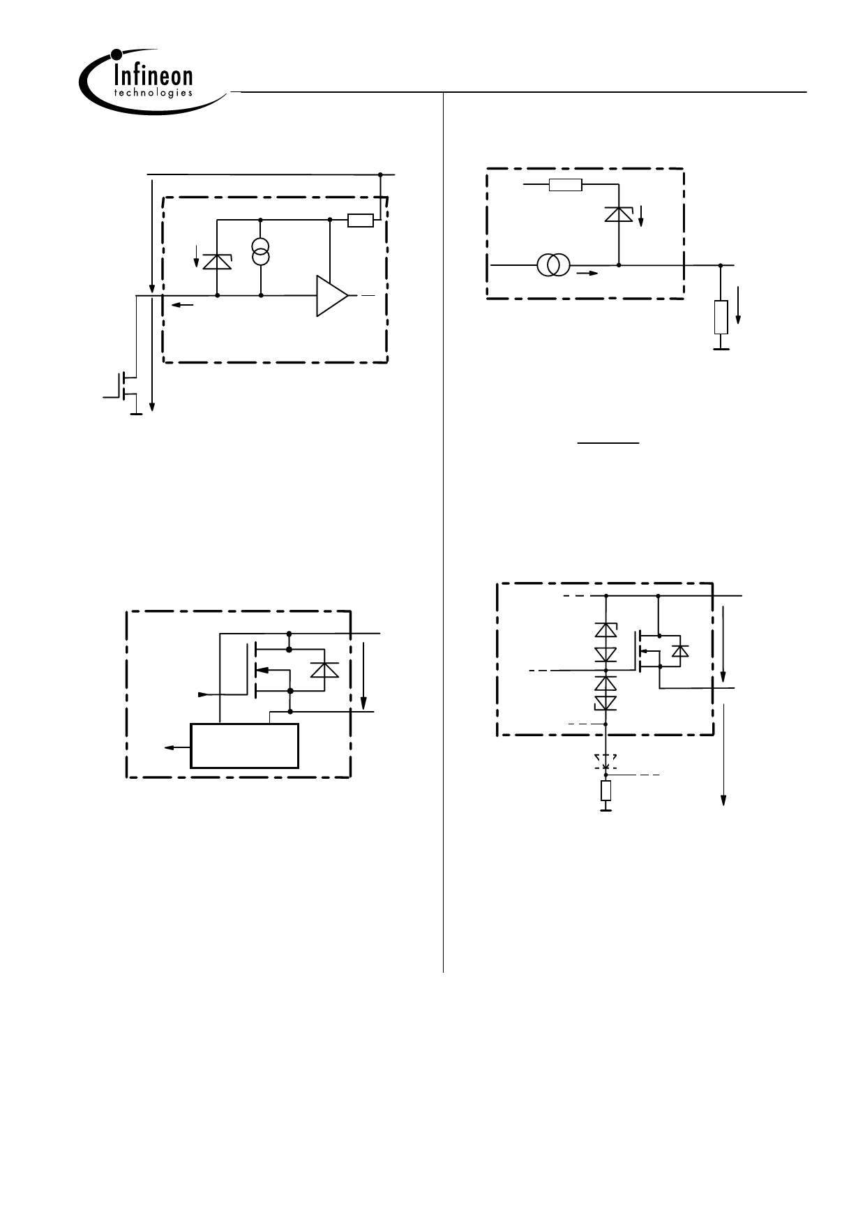
Input circuit (ESD protection)
Current sense status output
V
ZD
Z,IN
V bIN
IN
I
IN
V bb
R bb
Vbb
R bb
ZD
IIS
V
Z,IS
IS
VIS
R
IS
V IN
When the device is switched off (IIN = 0) the voltage
between IN and GND reaches almost Vbb. Use a
mechanical switch, a bipolar or MOS transistor with
appropriate breakdown voltage as driver.
VZ,IN = 66 V (typ).
Short circuit detection
Fault Condition: VON > VON(SC) (6 V typ.) and t> td(SC)
(80 ...350 µs).
+ Vbb
VON
Logic
unit
Short circuit
detection
OUT
VZ,IS = 66 V (typ.), RIS = 1 kΩ nominal (or 1 kΩ /n, if n
devices are connected in parallel). IS = IL/kilis can be
driven only by the internal circuit as long as Vout - VIS >
5 V. If you want measure load currents up to IL(M), RIS
should
be
less
than
Vbb -
IL(M) /
5V
Kilis.
Note: For large values of RIS the voltage VIS can reach
almost Vbb. See also over voltage protection.
If you don't use the current sense output in your
application, you can leave it open.
Inductive and over voltage output clamp
+ Vbb
VZ1
VON
VZG
IS
DS
OUT
PROFET
VOUT
VON is clamped to VON(Cl) = 42 V typ. At inductive load
switch-off without DS, VOUT is clamped to VOUT(CL) =
-19 V typ. via VZG. With DS, VOUT is clamped to Vbb -
VON(CL) via VZ1. Using DS gives faster deenergizing of
the inductive load, but higher peak power dissipation in
the PROFET. In case of a floating ground with a
potential higher than 19V referring to the OUT –
potential the device will switch on, if diode DS is not
used.
Infineon Technologies AG
Page 8
2003-Oct-01
Share Link: 