LTC1263CS8 Ver la hoja de datos (PDF) - Linear Technology
Número de pieza
componentes Descripción
Fabricante
LTC1263CS8 Datasheet PDF : 8 Pages
| |||
U
OPERATION
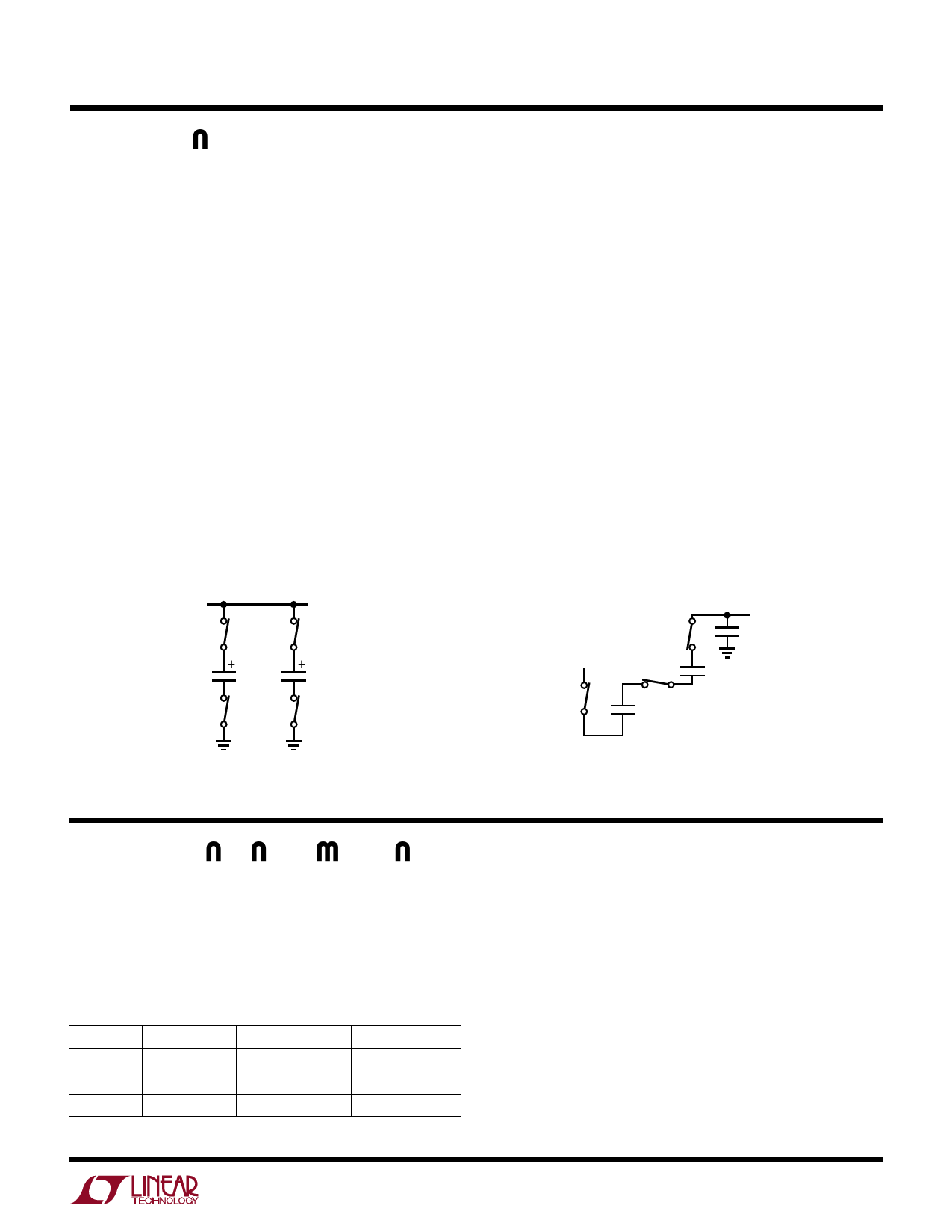
The LTC1263 uses a charge pump tripler to generate 12V
from a VCC of 5V. The charge pump is clocked by an
internal oscillator. The oscillator frequency is not critical
and may vary from the typical value of 300kHz. When the
oscillator output is low, C1 and C2 are each connected
between VCC and GND, charging them to VCC (see Figure
3). When the oscillator output goes high, C1 and C2 are
stacked in series with the bottom plate of C1 pulled to VCC
(see Figure 4). The top plate of C2 is switched to charge
COUT, which enables VOUT to rise.
VOUT is regulated to within 5% of 12V by an oscillator pulse
gating scheme that turns the charge pump on and off
based on the comparator results of VOUT and a reference
voltage. First, a resistor divider senses VOUT; if the output
of the divider (VDIV) is less than the output of a bandgap
(VBGAP) by the hysteresis voltage (VHYST) of the compara-
tor, then oscillator pulses are applied to the charge pump
to raise VOUT. When VDIV is above VBGAP by VHYST, the
LTC1263
oscillator pulses are prevented from clocking the charge
pump. As a result, VOUT drops until VDIV is below VBGAP by
VHYST again.
To ensure proper start-up when VOUT is lower than VCC
and maintain proper operation when VOUT is higher than
VCC, the gates of all internal switches are driven between
GND and the higher of either VOUT or VCC.
To reduce supply current, the LTC1263 may be put into
shutdown mode by “floating” the SHDN pin or connecting
it to VCC. In this mode, the bandgap, comparator, oscilla-
tor and resistor divider are switched off to reduce the
supply current to typically 0.5µA. At the same time an
internal switch shorts VOUT to VCC; VOUT takes 10ms (typ)
to reach 5.1V (see t OFF in Figure 1). When the SHDN pin
is low, the LTC1263 exits shutdown and the charge pump
operates to raise VOUT to 12V. VOUT takes 600µs (typ) to
reach the lower regulation limit of 11.4V (see tON in Figure 1).
VCC
C1
C2
LTC1263 • F03
Figure 3. C1 and C2 Charge to VCC
VCC
+
C1
+
C2
VOUT
COUT
LTC1263 • F04
Figure 4. C1 and C2 Stacked in Series with C1– Tied to VCC
APPLICATIONS INFORMATION
Choice of Capacitors
The LTC1263 is tested with the capacitors shown in Figure
2. C1 and C2 are 0.47µF ceramic capacitors and CIN and
COUT are 10µF tantalum capacitors. Refer to Table 1 if
other choices are desired.
Table 1. Recommended Capacitor Types and Values
CAPACITOR CERAMIC
TANTALUM
ALUMINUM
C1, C2 0.47µF to 1µF Not Recommended Not Recommended
COUT
10µF (Min)
CIN
10µF (Min)
10µF (Min)
10µF (Min)
10µF (Min)
10µF (Min)
C1 and C2 should be ceramic capacitors with values in the
range of 0.47µF to 1µF. Higher values provide better load
regulation. Tantalum capacitors are not recommended as
the higher ESR of these capacitors degrades performance
at high load currents and VCC = 4.75V.
CIN and COUT can be ceramic, tantalum or electrolytic
capacitors. The ESR of COUT introduces steps in the VOUT
waveform whenever the charge pump charges COUT. This
tends to increase VOUT ripple. Ceramic or tantalum capaci-
tors are recommended for COUT if minimum ripple is
5
Share Link: 