L6246 Ver la hoja de datos (PDF) - STMicroelectronics
Número de pieza
componentes Descripción
Fabricante
L6246 Datasheet PDF : 12 Pages
| |||
L6246
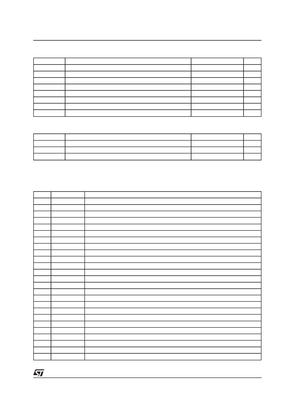
ABSOLUTE MAXIMUM RATINGS
Symbol
Vpow. max.
Vdigital max.
Vin max.
Vin min.
Ipeak
Idc
Ptot
Top
Parameter
Maximum supply voltage
Maximum supply voltage
Maximum input voltage
Minimum input voltage
Peak sink/source output current
DC sink/source output current
Maximum total power dissipation
Operative temperature range
Value
15
7
Vdigital ±0.3
GND - 0.3
3
1.7
≅1.7
0 to 80
Unit
V
V
V
V
A
A
W
°C
THERMAL DATA
Symbol
Rth j-case
Rth j-amb
Rth j-amb
Parameter
Thermal resistance junction to case
Thermal resistance junction to ambient mounted on standard PCB (*)
Thermal resistance junction to ambient mounted on PCB (**)
Value
≅20
≅66
≅35
Unit
°C/W
°C/W
°C/W
(*) Standard board construction: single layer (1S 0P); size 100mm long by 100mm wide.
(**) The board construction includes: a 6 layer board (2S 4P, with power planes ≅80%); size 136mm long by 99mm wide; package location
near middle point of lenght and one third of width.
PIN FUNCTIONS
Pin
Name
1
N.C.
2
Filter_cap
3
Brake Delay
4
-Thermal SD
5
Sense_in+
6
Sense_in-
7
Gnd
8
Err_out
9
Err-
10
Sense_out
11
N.C.
12
Vin_out
13
Vin-
14
Vin+
15
+Vcc/2
16
+Motor start
17 -AE_W_Gate
18
+Vdd
19
+Vcc
20
-POR
21
+5V Ref
22
T_cap
23
N.C.
24 +5V Ref Gnd
25
+5Setpt
Description
Not Connected.
Filter capacitor for 10V internal regulator. The capacitor is optional.
Voice Coil Motor brake delay capacitor.
Pre Thermal Shut Down indication Output.
Non inverting Input of Sense Amplifier.
Inverting Input of Sense Amplifier.
Ground.
Error Amplifier Output.
Inverting Input of Error Amplifier.
Output of Sense Amplifier.
Not Connected.
Output of Input Amplifier.
Inverting Input of Input Amplifier.
Non inverting Input of Input Amplifier.
Half Supply Voltage reference.
Motor start Output to Spindle Controller.
Write Gate Output to AE.
+5V Supply.
+12V Supply.
Power On Reset. Low will signal the failure of the logic supply or 12V supply
+5V Reference Output from the Voltage Reference Regulator.
Power On Reset Timing Capacitor. The capacitor sets the POR delay.
Not Connected.
Ground for Voltage Reference Generator.
+5V Monitor Set Point and filtering
3/12
Share Link: 