UT553B-RTIGCX Ver la hoja de datos (PDF) - Aeroflex UTMC
Número de pieza
componentes Descripción
Fabricante
UT553B-RTIGCX Datasheet PDF : 52 Pages
| |||
7
[0]
Channel B Enabled. A logic one indicates that Channel B is available for
both reception and transmission.
8
[0]
Channel A Enabled. A logic one indicates that Channel A is available for
both reception and transmission.
9
[1]
Terminal Flag Enabled. A logic one indicates that the Bus Controller has
not issued an Inhibit Terminal Flag mode code. A logic zero indicates that
the Bus Controller, via the above mode code, is overriding the host sys-
tem’s ability to set the Terminal Flag bit of the status word.
10
[0]
Busy. A logic one indicates the Busy bit is set. This bit is reset when the
SystemBusy bit in the Control Register is reset.
11
[0]
Self-Test. A logic one indicates that the RTI is in the self-test mode. This
bit isreset when the self-test is terminated.
12
[0]
TA Parity Error. A logic one indicates the wrong Terminal Address parity;
it causes the biphase inputs to be disabled and a message error condition.
This bit is reset by reloading the terminal address latch with correct parity.
13
[0]
Message Error. A logic one indicates that a message error has occurred
since the last System Register read. This bit is not reset until the System
Register has been examined and the message error condition is removed.
14
[0]
Valid Message. A logic one indicates that a valid message has been
received since the last System Register read. This bit is not reset until the
System Register has been examined.
15
[0]
Terminal Active. A logic one indicates the device is executing a transmit or
receive operation. The state of this bit is the logical NAND of the external
XMIT and RCV pins.
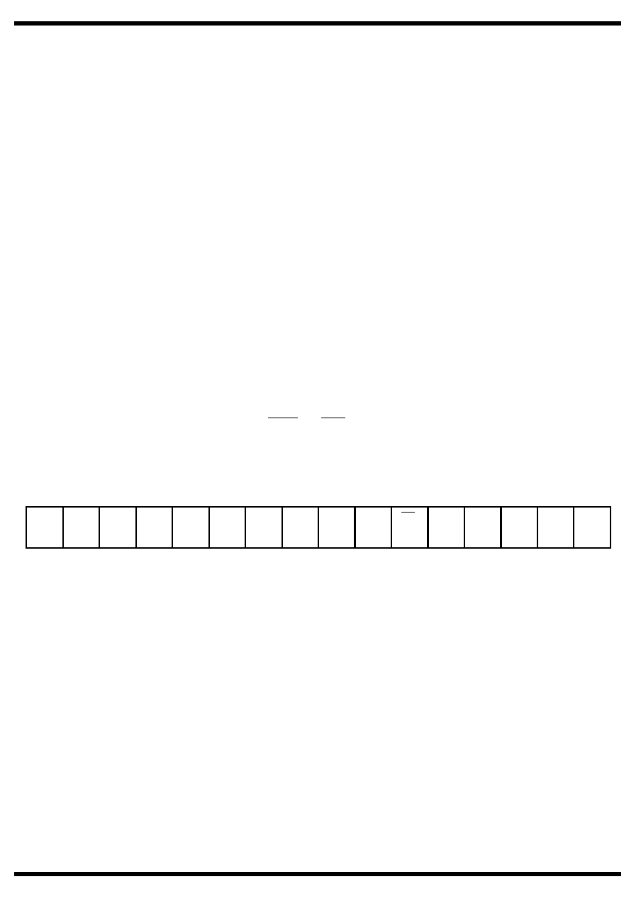
SYSTEM REGISTER (READ ONLY)
TERM VAL MESS TAPA SELF- BUSY TFEN CH A CH B CHNL MC/ MCSA MCSA MCSA MCSA MCSA
ACTV MESS ERR ERR TEST
EN
EN
A/B SA
4
3
2
1
0
[0]
[0] [0]
[0]
[0]
[0]
[1]
[0]
[0]
[1]
[0]
[0]
[0]
[0]
[0]
[0]
MSB
LSB
[ ] defines reset state
Figure 5. System Registers
RTI-6
Share Link: 