UT553B-RTIGCX Ver la hoja de datos (PDF) - Aeroflex UTMC
Número de pieza
componentes Descripción
Fabricante
UT553B-RTIGCX Datasheet PDF : 52 Pages
| |||
The 8-bit write-only Control Register manages the operation of the RTI. Write to the Control Register by applying a logic zero
to CS, CTRL, RD/WR, and ADDR IN (0); if ADDR IN (0) is a logic one a master reset occurs. Data is loaded into the Control
Register via I/O pins DATA(7:0). Control Register writes must occur 50ns before the rising edge of COMSTR to latch data in
the outgoing status word.
Bit
Number
Initial
Condition
Description
0
[0]
Channel A Enable. A logic one enables Channel A biphase inputs.
1
[0]
Channel B Enable. A logic one enables Channel B biphase inputs.
2
[0]
Terminal Flag. A logic one sets the Terminal Flag bit of the Status Register.
3
[0]
System Busy. A logic one sets the Busy bit of the System Register and inhibits
RTI access to memory. No data words are retrieved or stored; command word is
stored.
4
[0]
Subsystem Busy. A logic one sets the Subsystem Flag bit of the Status Register.
5
[0]
Self-Test Channel Select. This bit selects which channel the internal self-test
checks; a logic one selects Channel A and a logic zero selects Channel B.
6
[0]
Self-Test Enable. A logic one sets the RTI in the internal self-test mode and inhib-
its normal operation. Internal testing is not visible on biphase output
channels.
7
[0]
Service Request. A logic one sets the Service Request bit of the Status Register.
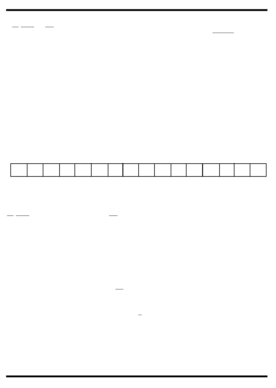
CONTROL REGISTER (WRITE ONLY)
XXXX X
MSB
[ ] defines reset state
X
XX
SRV
RQ
SELF SELF SUBS BUSY
TEST CH
TF CH B CH A
EN
EN
[0]
[0]
[0]
[0]
[0]
[0]
[0]
[0]
LSB
Figure 4. Control Register
System Register (Read Only)
The 16-bit read-only System Register provides the RTI system status. Read the System Register by applying a logic zero to
CS, CTRL, ADDR IN (0), and a logic one to RD/WR. The 16-bit contents of the System Register are read from data I/O pins
DATA(15:0).
Bit
Number
Initial
Condition
Description
0
[0]
MCSA(0). The LSB of the mode code or subaddress as indicated by the
logic state of bit 5.
1
[0]
MCSA(1). Mode code or subaddress as indicated by the state of bit 5.
2
[0]
MCSA(2). Mode code or subaddress as indicated by the state of bit 5.
3
[0]
MCSA(3). Mode code or subaddress as indicated by the state of bit 5.
4
[0]
MCSA(4). Mode code or subaddress as indicated by the state of bit 5.
5
[0]
MC/SA. A logic one indicates that bits 4 through 0 are the subaddress of
the last command word, and that the last command word was a normal
transmit orreceive command. A logic zero indicates that bits 4 through 0
are a mode code, and that the last command was a mode code.
6
[1]
Channel A/B. A logic one indicates that the most recent command arrived
onChannel A; a logic zero indicates that it arrived on Channel B.
RTI-5
Share Link: 