HS-82C37ARH(1995) Ver la hoja de datos (PDF) - Intersil
Número de pieza
componentes Descripción
Fabricante
HS-82C37ARH Datasheet PDF : 29 Pages
| |||
HS-82C37ARH
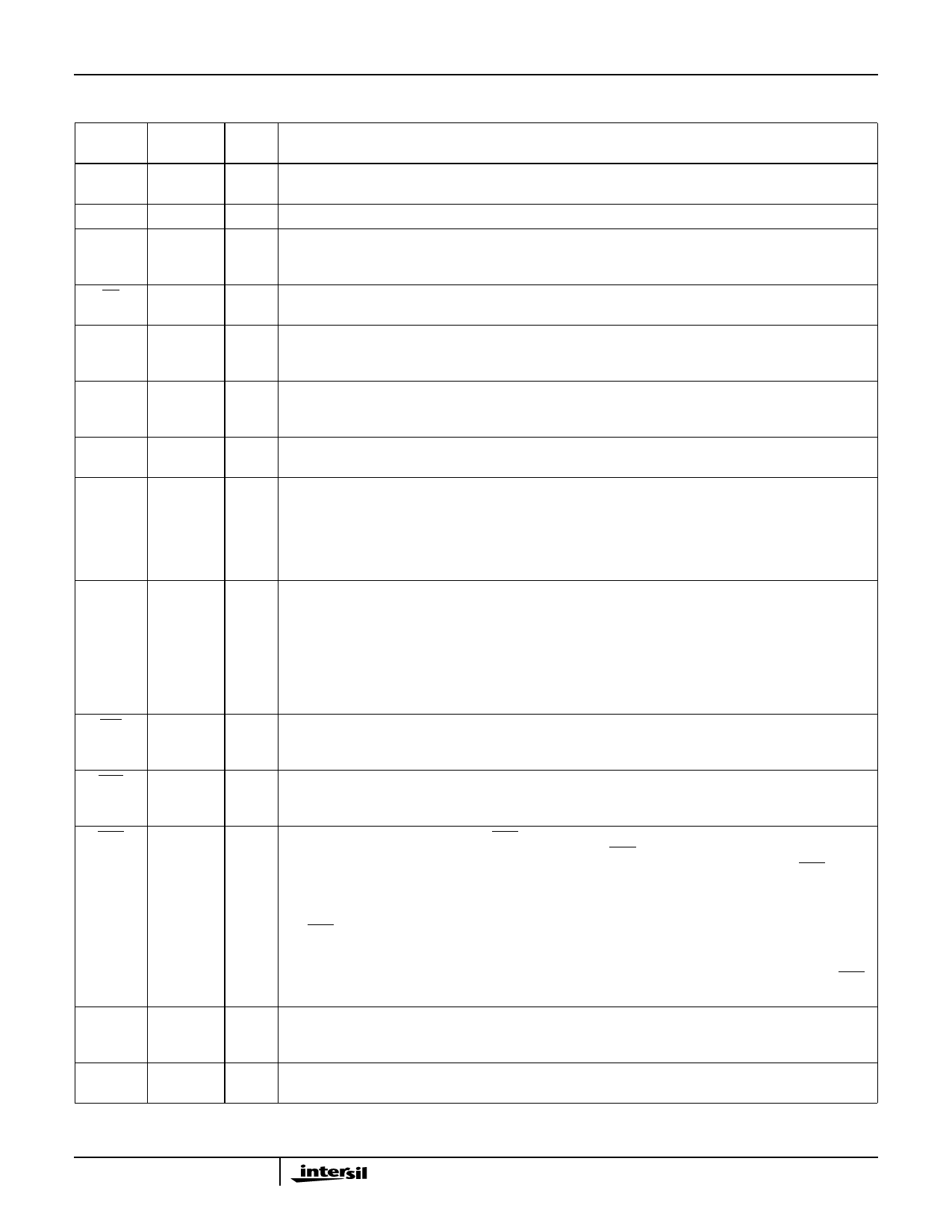
Pin Descriptions
PIN
SYMBOL NUMBER TYPE
DESCRIPTION
VDD
31
VDD: is the +5V power supply pin. A 0.1µF capacitor between pins 31 and 20 is recommended for de-
coupling.
GND
20
Ground
CLK
12
I
CLOCK INPUT: The Clock Input is used to generate the timing signals which control HS-82C37ARH
operations. This input may be driven from DC to 5MHz and may be stopped in either high or low state
for standby operation.
CS
11
I
CHIP SELECT: Chip Select is an active low input used to enable the controller onto the data bus for
CPU communications.
RESET
13
I
RESET: This is an active high input which clears the Command, Status, Request and Temporary Reg-
isters, the First/Last Flip-Flop, and the Mode Register Counter. The Mask Register is Set to ignore re-
quests. Following a Reset, the controller is in an idle cycle.
READY
6
I
READY: This signal can be sued to extend the memory read and write pulses from the HS-82C37ARH
to accommodate slow memories or I/O devices. Ready must not make transitions during its specified
set-up and hold times. Ready is ignored in Verify Transfer mode.
HLDA
7
I
HOLD ACKNOWLEDGE: The active high Hold Acknowledge from the CPU indicates that is has relin-
quished control of the system busses.
DREQ0-
DREQ3
16-19
I
DMA REQUEST: The DMA Request (DREQ) lines are individual asynchronous channel request inputs
used by peripheral circuits to obtain DMA service. In Fixed Priority, DREQ0 has the highest priority and
DREQ3 has the lowest priority. A request is generated by activating the DREQ line of a channel. DACK
will acknowledge the recognition of DREQ signal. Polarity of DREQ is programmable. Reset initializes
these lines to active. DREQ will not be recognized while the clock is stopped. Unused DREQ inputs
should be pulled High or Low (inactive) and the corresponding mask bit set.
DB0-
DB7
21-23
26-30
I/O DATA BUS: The Data Bus lines are bidirectional three-state signals connected to the system data bus.
The outputs are enabled in the Program Condition during the I/O Read to output the contents of a reg-
ister to the CPU. The outputs are disabled and the inputs are read during an I/O Write cycle when the
CPU is programming the HS-82C37ARH Control Registers. During DMA cycles, the most significant 8
bits of the address are output onto the data bus to be strobed into an external latch by ADSTB. In Mem-
ory-to-Memory operations, data from the memory enters the HS-82C37ARH on the data bus during the
read-from-memory transfer, then during the write-to-memory transfer, the data bus outputs write the
data into the new memory location.
IOR
1
I/O I/O READ: I/O Read is a bidirectional active low three-state line. In the Idle cycle, it is an input control
signal used by the CPU to read the internal registers. In the Active cycle, it is an output control signal
used by the HS-82C37ARH to access data from a peripheral during a DMA Write transfer.
IOW
2
I/O I/O WRITE: I/O Write is a bidirectional active low three-state line. In the Idle cycle, it is an input control
signal used by the CPU to load information into the HS-82C37ARH. In the Active cycle, it is an output
control signal used by the HS-82C37ARH to load data to the peripheral during a DMA Read transfer.
EOP
36
I/O END OF PROCESS: End of Process (EOP) is an active low bidirectional signal. Information concerning
the completion of DMA services is available at the bidirectional EOP pin.
The HS-82C37ARH allows an external signal to terminate an active DMA service by pulling the EOP
pin low. A pulse is generated by the HS-82C37ARH when terminal count (TC) for any channel is
reached, except for channel 0 in Memory-to-Memory mode. During Memory-to-Memory transfers, EOP
will be output when the TC for channel 1 occurs.
The EOP pin is driven by an open drain transistor on-chip, and requires an external pull-up resistor.
When an EOP pulse occurs, whether internally or externally generated, the HS-82C37ARH will termi-
nate the service, and if Autoinitialize is enabled, the base registers will be written to the current registers
of that channel. The mask bit and TC bit in the Status Register will be set for the currently active channel
by EOP unless the channel is programmed for Autoinitialize. In that case, the mask bit remains clear.
A0-A3
32-35
I/O Address: The four least significant address lines are bidirectional three-state signals. In the Idle cycle,
they are inputs and are used by the HS-80C86RH to address the internal registers to be loaded or read.
In the Active cycle, they are outputs and provide the lower 4 bits of the output address.
Spec Number 518058
920
Share Link: 