UT1750AR12WCC(2003) Ver la hoja de datos (PDF) - Aeroflex UTMC
Número de pieza
componentes Descripción
Fabricante
UT1750AR12WCC Datasheet PDF : 55 Pages
| |||
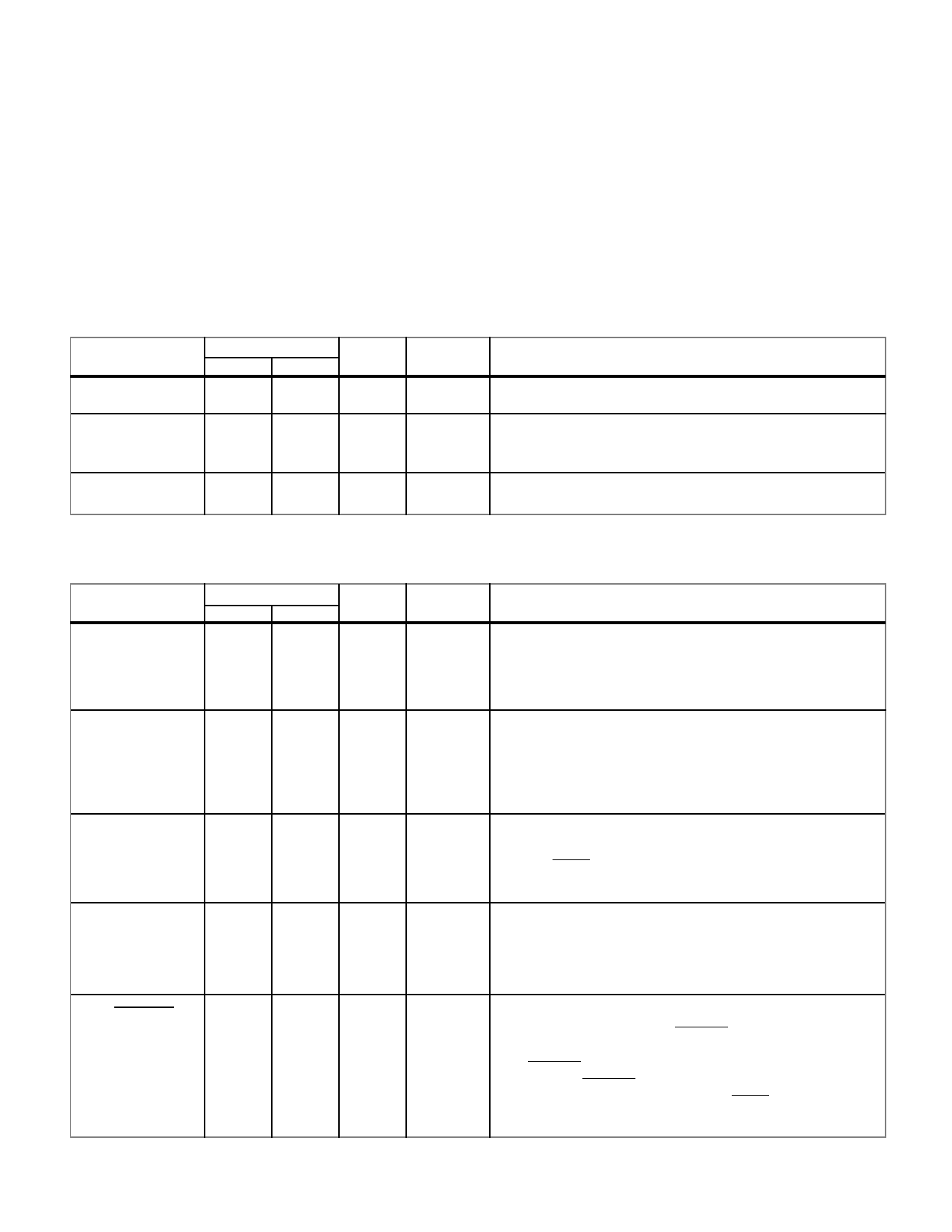
FUNCTIONAL PINOUT
Legend for TYPE and ACTIVE fields:
TO = TTL output
TI = TTL input
TUI = TTL input (pull-up)
TDI = TTL input (pull-down)
TTO = Three-state TTL output
TTB = Three-state TTL bidirectional
CO = CMOS output
OSC = Oscillator input to a Pierce Oscillator inverter
AH = Active High
AL = Active Low
OSCILLATOR AND CLOCK SIGNALS
PIN NAME
OSCIN
OSCOUT
SYSCLK
PIN NUMBER
FLTPK PGA
50
P14
51
P15
52
M14
TYPE
OSC
ACTIVE
--
CO
--
DESCRIPTION
Oscillator Input. A 50% duty cycle crystal-drive input for
driving the UT1750AR.
Oscillator Output. A 50% duty cycle, single-phase clock
output at the same frequency as the OSCIN input.
TO
--
System Output. The buffered equivalent of the OSCOUT
signal.
PROCESSOR STATUS
PIN NAME
NUI1
PIN NUMBER
FLTPK PGA
129
H2
TYPE ACTIVE
TI
--
DESCRIPTION
Not used input 1. Internal UTMC use only. Tie either high
or low.
NUI2
44
P12
TUI
--
Not used input 2. Internal UTMC use only. Tie low.
NUO3
M1750
STATE1
126
G3
TTO
--
Not used output 3. Internal UTMC use only. NUO3 enter
high impedance state when the UT1750AR is in the test
mode (TEST=0)
45
N11
TDI
AH
Mode Select RISC/1750. A high on M1750 places the
UT1750AR into the MIL-STD-1750A emulation mode.
A low on M1750 places the UT1750AR into the RISC
mode. It is tied to an internal pull-down resistor.
54
N15 TTO
--
Processor State. This signal indicates the internal state of
the UT1750AR. A low on STATE1 indicates the
UT1750AR is executing a new RISC instruction. A high
on STATE1 indicates the UT1750AR is fetching a RISC
instruction. STATE1 enters a high-impedance state when
the UT1750AR is in the test mode (TEST=0).
4
Share Link: 