MX809J Ver la hoja de datos (PDF) - MX-COM Inc
Número de pieza
componentes Descripción
Fabricante
MX809J Datasheet PDF : 22 Pages
| |||
MSK Modem
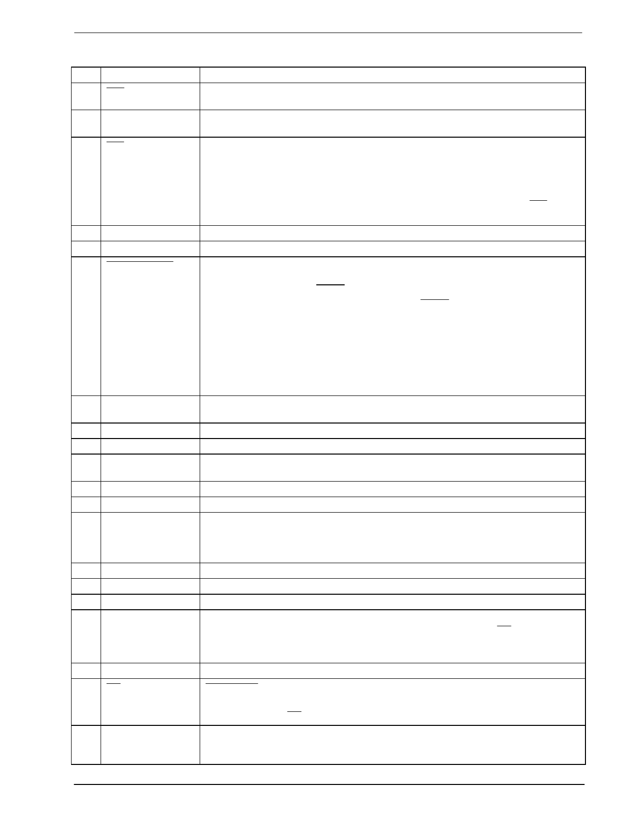
2 Signal List
Pin
Signal
1 Xtal
2 Xtal/Clock
3 IRQ
4 N/C
5 N/C
6 RX Freeformat
7 VBIAS
8 Amp In
9 Amp Out
10 RX In
11 N/C
12 VSS
13 TX Out
14 N/C
15 N/C
16 N/C
17 Reply Data
18 N/C
19 CS
20 Command Data
4
MX809
Description
This is the output of the on-chip clock oscillator. External components are
required at this output when a Xtal is used. See Figure 2. Inset
This is the input to the on-chip clock oscillator inverter. A Xtal or externally
derived clock should be connected here. See Figure 2. Inset
The output of this pin indicates an interrupt condition to the microcontroller by
going to a logic “0”. This is a “wire-or-able” output that enables the connection of
up to 8 peripherals to 1 interrupt port on the microcontroller. This pin is an open-
drain output, and therefore has a low impedance pulldown to logic “0” when active
and a high impedance when inactive. The conditions that cause interrupts are
indicted in the Status Register and are shown in Table 2. The system IRQ line
requires a pull-up resistor to VDD.
When this input is logic “0” in the RX Mode, it allows received data to be read
from the RX Data Buffer via the Reply Data line without having to achieve byte
synchronization (SYNC/ SYNC ) first. Data will continue to be available after this
input goes to a logic “1” until either a SYNC or SYNC Prime Bit is set or the
modem is set to TX Mode. When held at a logic “1” the modem operates
normally. This pin has an internal 1M pull-up resistor.
Note: If this input is held at a logic “0” in the TX Mode, the RX Data Ready bit in
the Status Register may occasionally be set, but not cause an interrupt. If this
input is a logic “0” when going into the RX Mode, and RX Data Ready interrupt
may be generated immediately (in this case the first byte of RX data should be
ignored).
The internal circuitry bias line, this is held at VDD/2. This pin must be decoupled
to VSS by capacitor C3. See Figure 2.
The inverting input to the on-chip uncommitted amplifier.
The output of the on-chip uncommitted amplifier.
This is the 1200 baud, 1200Hz/1800Hz received MSK signal input. The input
signal to this pin must be AC coupled via capacitor C4. See Figure 2.
Negative Supply (GND)
This is the 1200 baud, 1200Hz/1800Hz MSK TX output. When not transmitting
data the output impedance of this pin is high. On power-up this output can be any
level. A General Reset command is required to ensure that this output attains
VBIAS initially.
This is the C-BUS serial data output to the microcontroller. The transmission of
Reply Data bytes is synchronized to the Serial Clock under the CS input. This 3-
state output is held high impedance when not sending data to the microcontroller.
See Section 6 and Section 7.1.4.
Chip Select . This is the ‘C-BUS’ data loading control function. This input is
provided by the microcontroller. Data transfer sequences are initiated, completed
or aborted by the CS signal. See Section 6 and Section 7.1.4.
This is the ‘C-BUS’ serial data input from the microcontroller. Data is loaded to
this device in 8-bit bytes, MSB (bit 7) first and LSB (bit 0) last, synchronized to the
Serial Clock. See Section 6 and Section 7.1.4.
1998 MX-COM, Inc.
www.mxcom.com Tel: 800 638 5577 336 744 5050 Fax: 336 744 5054
Doc. # 20480036.004
4800 Bethania Station Road, Winston-Salem, NC 27105-1201 USA
All trademarks and service marks are held by their respective companies.
Share Link: 