LA7780M Ver la hoja de datos (PDF) - SANYO -> Panasonic
Número de pieza
componentes Descripción
Fabricante
LA7780M Datasheet PDF : 9 Pages
| |||
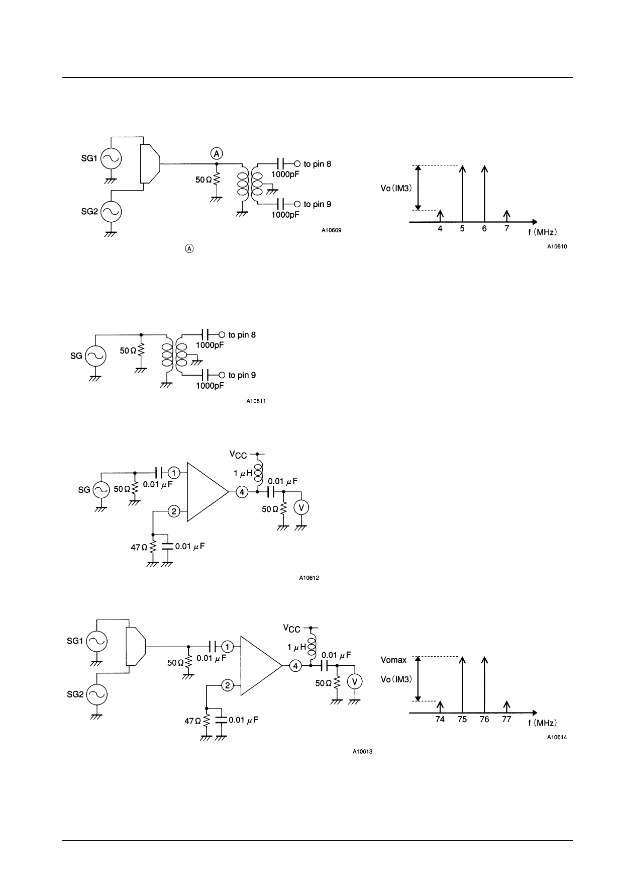
Note 2.
Input: SG1 = 69.55 MHz, SG2 = 70.55 MHz
LA7780M
Other conditions:
Internal AGC mode
Pin 24 left open.
Output: The post amplifier output (pin 13)
Point = 20 dBmV (69.55 MHz) + 20 dBmV (70.55 MHz)
Note 3.
Post amplifier output level = –3 dB
Remove the low-pass filter between pins 14 and 16.
(Short the coil of 27 µH and remove the capacitors of 27 pF and 15 pF.)
Note 4.
Input: SG1 = 69.55 MHz
Other conditions:
Internal AGC mode
Pin 24 left open.
Output: The signal level such that the post
amplifier output (pin 13) falls by –3 dB.
Note 5.
SG = 75 MHz, 20 dBm V
Note 6.
SG1 = 75 MHz, SG2 = 76 MHz,
Adjust the pin 1 level until the IM3 in the pin 4 output is 40 dB.
Output:RF1-OUT (pin 4)
VO(IM3) = 40 dB
No. 5268-3/9
Share Link: 