SA9607PPA Ver la hoja de datos (PDF) - South African Micro Electronic Systems
Número de pieza
componentes Descripción
Fabricante
SA9607PPA
South African Micro Electronic Systems

SA9607PPA Datasheet PDF : 12 Pages
| |||
SA9607P
FUNCTIONAL DESCRIPTION
The SA9607P is a CMOS mixed signal analog/digital integrated
circuit, which performs power/energy calculations across a
power range of 1000:1, to an overall accuracy of better than
Class 1.
The integrated circuit includes all the required functions for
single phase power and energy measurement such as
oversampling A/D converters for the voltage and current
sense inputs, power calculation and energy integration. Internal
offsets are eliminated through the use of cancellation
procedures. The SA9607P incorporates an anti-tamper scheme
by continuously measuring the power consumption on both
LIVE and NEUTRAL lines. A fault is indicated when these
measurements differ by more than 12.5%. The SA9607P
generates pulses with a frequency proportional to the larger of
the two current measurements. The source (LIVE or NEUTRAL)
for these pulses is indicated on the SEL1 pin.
Various pulse outputs (MOP, MON and LED) are available.
The pulse rate on these pins follows the active power
consumption measured.
A low voltage stepper may be driven directly from the device
by connecting it between the MOP and MON pins, alternatively
an impulse counter may be driven directly by connecting it
between MOP and V .
SS
The SA9607P configures itself from an external low cost
EEPROM that contain all meter configurations and calibration
data. No external trimming is required for this device. Calibration
of the device may be fully automated.
POWER CALCULATION
In Figure 7, the voltage drop across the current transformers
terminating resistor will be between 0 and 16mVRMS. These
voltages are converted to currents for each current sense
input, by means of resistors R1 and R2 (channel 1) as well as
R3 and R4. (channel 2).
The current sense input saturates at an input current of ±25µA
peak. The mains voltage (230VAC) is divided down through a
divider to 14VRMS. The current into the A/D converter input is
set
at
14µA
RMS
at
nominal
mains
voltage,
via
resistor
R
6
(1MΩ).
See Device Configuration for more details on the processing
of measured energy to frequency outputs.
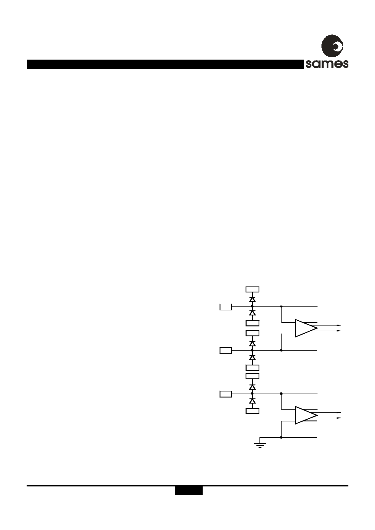
ANALOG INPUT CONFIGURATION
The input circuitry of the current and voltage sensor inputs are
illustrated in figure 3. These inputs are protected against
electrostatic discharge through clamping diodes.
The feedback loops from the outputs of the amplifiers A and
I
AV generate virtual shorts on the signal inputs. Exact
duplications of the input currents are generated for the analog
signal processing circuitry.
AUTOMATIC DEVICE CONFIGURATION (BOOT UP)
During power up, registers containing configuration and
calibration information is updated from an external EEPROM.
The device itself never writes to the EEPROM so any write
protect features offered by manufacturer of EEPROM's may
be used to protect the configuration and calibration constants
of the meter. The device reloads its configuration every 1193
seconds from the external EEPROM in order to ensure correct
operation of the meter. Every data byte stored in the EEPROM
is protected with a checksum byte to ensure data integrity.
ELECTROSTATIC DISCHARGE (ESD)
PROTECTION
The SA9607P integrated circuit's input's/outputs are protected
against ESD.
POWER CONSUMPTION
The power consumption rating of the SA9607P integrated
circuit is less than 30mW.
V DD
IIP
CURRENT
V SS
SENSOR
INPUTS
V DD
IIN
VSS
VDD
IVP
VOLTAGE
SENSOR
V SS
INPUT
AI
AV
DR-01288
GND
Figure 3: Analog Input Internal Configuration
http://www.sames.co.za.
4/12
Share Link: