MH88630 Ver la hoja de datos (PDF) - Mitel Networks
Número de pieza
componentes Descripción
Fabricante
MH88630 Datasheet PDF : 10 Pages
| |||
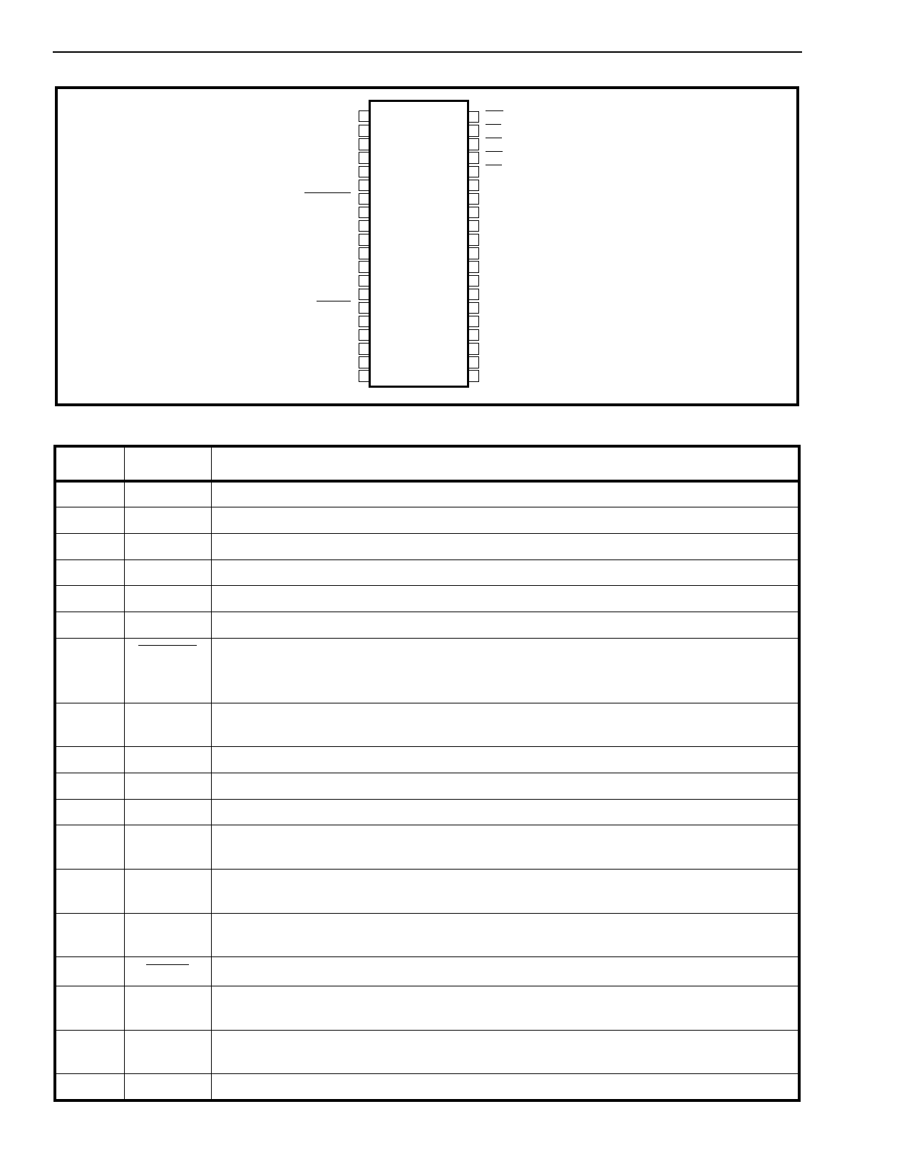
MH88630
Preliminary Information
IC 1
T2
R3
IC 4
IC 5
LPGND 6
RINGND 7
VTR+ 8
QE 9
QB 10
VTR- 11
XA 12
XB 13
XC 14
RGND 15
RC1 16
RD1 17
CD 18
RD2 19
RC2 20
40 RG
39 FC
38 RV
37 RC
36 TG
35 VDD
34 VEE
33 AGND
32 RXIN-
31 RXIN+
30 NETBAL
29 VX
28 GSX
27 TXIN+
26 TXIN-
25 VCC-
24 VCC+
23 RXOUT
22 GSR
21 VR
Pin Description
Figure 2 - Pin Connections
Pin #
Name
Description
1
IC
Internal Connection. Pin cut short. Leave open circuit.
2
T
Tip (Input). Normally connects to the “Tip” lead of the C.O.
3
R
Ring (Input). Normally connects to the “Ring” lead of the C.O.
4
IC
Internal Connection. Leave open circuit.
5
IC
Internal Connection. Leave open circuit.
6
LPGND Loop Ground is the system ground reference with respect to -48 volts.
7
RINGND Ring Ground (Input). For Ground Start Trunk only, a logic low input will enable the trunk
circuit to ground the Ring lead through a low resistance (390Ω). This is a signal to the
C.O. that the interface is seizing the line.
8
VTR+ Connects to the collector of an external transistor (Q1) and TXIN - (pin 26) via an
external capacitor.
9
QE
Connects to the emitter of an external transistor (Q1).
10
QB
Connects to the base of an external transistor (Q1).
11
VTR- Connects to the TXIN+ (pin 27), via an external capacitor (C1).
12
XA
External relay contact (K1) connection from VTR+ (pin 8), activated by loop seize control
input (RC1).
13
XB
External relay contact (K1) connection from XC (pin 14), activated by loop seize control
input (RC1).
14
XC
External relay contact (K1) connection from XB (pin 13), activated by loop seize control
input (RC1).
15
RGND Relay Ground.
16
RC1 Relay Control 1 (Input). A logic high will activate the relay (K1) to provide loop seize
across Tip and Ring.
17
RD1 Relay Driver 1 (Output): Open collector sinks current when RC1 is high. Diode clamp
protected.
18
CD
Clamping Diode: Normally connects to the positive supply voltage.
2-216
Share Link: 