ICL7109 Ver la hoja de datos (PDF) - Intersil
Número de pieza
componentes Descripción
Fabricante
ICL7109 Datasheet PDF : 25 Pages
| |||
ICL7109
+5V
GND
+5V
+5V
+5V
+5V
2
XTAL1
1 TO
3
XTAL2
4 RESET
5 SS
6 INT
21 - 24
35 - 38
P20 - P27
/8
7 EA
8 WR
9 PSEN
11 ALE
25 PROG
26 VDD
39 TL
31 - 34
P14 - P17
/5
8748/9048
P13 30
P12 29
P11 28
P10 27
40 VCC
OTHER
I/O
12 - 19
DB0 - DB7
8/
GND 20 GND
RD 10
+5V 40 V+
GND 1 GND
REF IN - 39
+5V 17 TEST
REF CAP- 38
REF CAP+ 37
REF IN+ 36
ICL7109
IN HI 35
IN LO 34
COMMON 33
INT 32
AZ 31
26 RUN/HOLD
BUF 30
2 STATUS REF OUT 29
18 LBEN
V- 28
19 HBEN
SEND 27
RUN/HOLD 26
BUFF OSC OUT 25
6/
3-8
B9 - B12,
OSC SEL 24
POL,OR
OSC OUT 23
8
/
9 - 16
B1 - B8
OSC IN 22
20 CE/LOAD
MODE 21
- GND
1µF
EXTERNAL
REFERENCE
1MΩ
0.01µF
+
+
INPUT
-
CAZ
0.33µF
CINT
0.15µF
GND
RINT 20kΩ 0.2V REF
200kΩ 2V REF
-5V
+5V
+5V OR OPEN
GND
3.58MHz
CRYSTAL
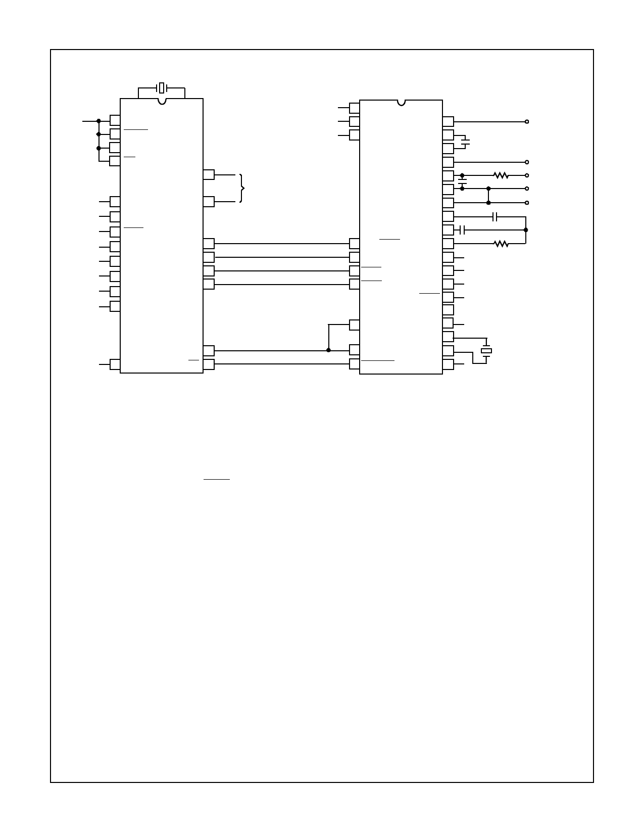
FIGURE 1B. TYPICAL CONNECTION DIAGRAM PARALLEL INTERFACE WITH 8048 MICROCOMPUTER
FIGURE 1.
Detailed Description
Analog Section
Figure 2 shows the equivalent circuit of the Analog Section
for the ICL7109. When the RUN/HOLD input is left open or
connected to V+, the circuit will perform conversions at a
rate determined by the clock frequency (8192 clock periods
per cycle). Each measurement cycle is divided into three
phases as shown in Figure 3. They are (1) auto-zero (A-Z),
(2) signal integrate (INT) and (3) de-integrate (DE).
Auto-Zero Phase
During auto-zero three things happen. First, input high and
low are disconnected from the pins and internally shorted to
analog COMMON. Second, the reference capacitor is
charged to the reference voltage. Third, a feedback loop is
closed around the system to charge the auto-zero capacitor
CAZ to compensate for offset voltages in the buffer amplifier,
integrator, and comparator. Since the comparator is included
in the loop, the A-Z accuracy is limited only by the noise of
the system. In any case, the offset referred to the input is
less than 10µV.
Signal Integrate Phase
During signal integrate, the auto-zero loop is opened, the
internal short is removed, and the internal input high and low
are connected to the external pins. The converter then
integrates the differential voltage between IN HI and IN LO
for a fixed time. This differential voltage can be within a wide
common mode range of the inputs. At the end of this phase,
the polarity of the integrated signal is determined.
8
Share Link: 