LB1872 Ver la hoja de datos (PDF) - SANYO -> Panasonic
Número de pieza
componentes Descripción
Fabricante
LB1872 Datasheet PDF : 11 Pages
| |||
LB1872
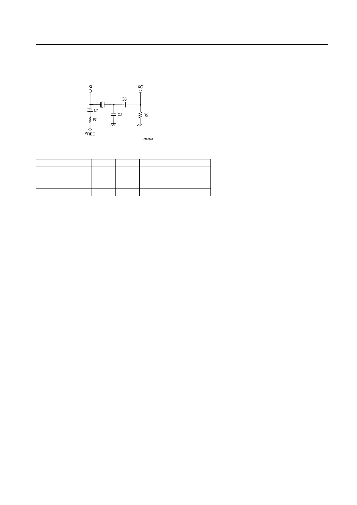
4. Reference clock
Any one of the following three techniques can be used to input the reference clock used for speed control.
• Crystal oscillator generated clock
Use the following circuit, consisting of a crystal element, capacitors, and resistors, as a crystal oscillator circuit.
C1 and R1: Used for oscillator stabilization.
C3: Used for oscillator element coupling.
C2: Used for overtone prevention.
R2: Improves the oscillator margin.
Sample External Component Values
Oscillator frequency (MHz)
1 to 3
3 to 5
5 to 7
7 to 10
C1 (µF)
0.1
0.1
0.1
0.1
C2 (pF)
47
18
—
—
C3 (pF)
220
100
47
33
R1 (Ω)
220 k
100 k
47 k
10 k
R2 (Ω)
—
—
—
4.7 k
This circuit and these component values are only provided for reference purposes. Consult with the manufacturer of
the crystal element concerning the influence of such factors as the characteristics of the crystal element itself and the
stray capacitances due to the printed circuit board wiring pattern to assure that problems do not occur.
(Notes on printed circuit board wiring)
Since crystal oscillator circuits are high-frequency circuits, they are easily influenced by stray capacitances due to the
printed circuit board wiring. Therefore, lines for external components must be kept as short as possible and lines must
be made as narrow as possible. In this external circuit, the connection between the oscillator element and C3 (and C2)
is particularly subject to influence by stray capacitance, and requires special care.
• External clock (crystal oscillator equivalent: a few MHz)
If a signal equivalent to a crystal oscillator signal is input from an external signal generator, input that signal
through a series resistor of about 13 kΩ to the XI pin. Leave the XO pin open.
• External clock (FG frequency equivalent: a few kHz)
If a signal equivalent to the FG frequency is input from an external signal generator, set the N2 pin to the middle
level (or open) and input that signal to the N1 pin. In this case, the motor will remain in the stopped state (short-
circuit braking operation) even if a start input is applied when no clock is input. However, since IC heating due to
the large output drive currents that flow in the short braking state (since the lower side transistors in all phases are
driven) care is required if the braking state must be held for extended periods.
5. Hall input signals
Even if the amplitude of the Hall sensor input signals is changed by the motor, the influence on the output will be
suppressed by the AGC circuit. However, if there are discrepancies between the amplitudes of the three phases, the
output phase switching timing may be shifted.
The output current will be cut off by a protection circuit if a start signal is input when there are no signals applied to
the Hall inputs.
The maximum operating frequency of the Hall inputs is affected by the saturation state of the outputs. While there are
no problems for frequencies of under 1 kHz (the frequency in a single Hall phase), if a higher operating frequency is
required, it can be advantageous if the outputs remain unsaturated. If the outputs remain in the unsaturated state, this
IC can be used up to frequencies of about 2 kHz.
Since motors with higher speeds have higher operating frequencies, we recommend using motors with four motor
magnet poles.
6. LD output
The LD output goes on when the phase is locked. Phase lock is determined not by the speed error but by the phase
error only. Therefore, the speed error when the LD output is on, during, for example, lock pull-in, will change with
the acceleration of the FD signal. (The speed error will be smaller for lower accelerations.) If it is necessary to
No. 5625-10/11
Share Link: 