PS2651-V Ver la hoja de datos (PDF) - NEC => Renesas Technology
Número de pieza
componentes Descripción
Fabricante
PS2651-V Datasheet PDF : 4 Pages
| |||
PS2651, PS2651L2, PS2652, PS2652L2
ABSOLUTE MAXIMUM RATINGS1 (TA = 25°C)
SYMBOLS
PARAMETERS
Diode
VR Reverse Voltage
IF
Forward Current
PD Power Dissipation
IF (Peak) Peak Forward Current
PW = 100 µs, Duty Cycle 1%
Transistor
VCEO Collector to Emitter Voltage
VECO Emitter to Collector Voltage
IC
Collector Current
PC Power Dissipation
Coupled
BV Isolation Voltage2
TSTG Storage Temperature
TOP Operating Temperature
UNITS
V
mA
mW
A
V
V
mA
mW
Vr.m.s.
°C
°C
RATINGS
6
80
150
1
80
7
50
150
5000
-55 to +150
-55 to +100
Notes:
1. Operation in excess of any one of these parameters may result in
permanent damage.
2. AC voltage for 1 minute at TA = 25 °C, RH = 60 % between input
(Pin No. 1, 2, 3 Common) and output (Pin No. 4, 5, 6 Common).
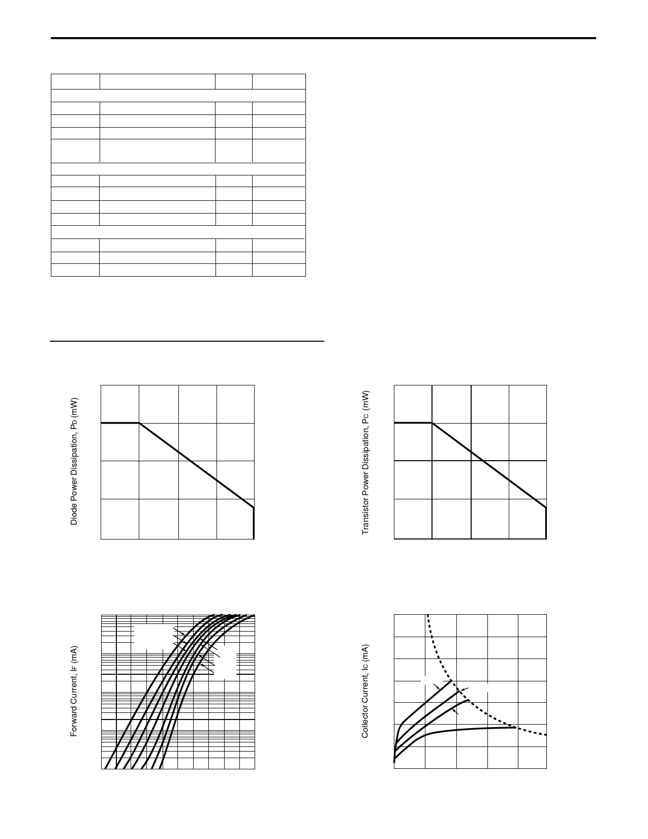
TYPICAL PERFORMANCE CURVES (TA = 25 °C)
DIODE POWER DISSIPATION
vs. AMBIENT TEMPERATURE
200
150
100
50
0
25
50
75
100
Ambient Temperature, TA (°C)
FORWARD CURRENT vs.
FORWARD VOLTAGE
100
TA = 100 ˚C
75 ˚C
50 ˚C
10
25 ˚C
0 ˚C
-25 ˚C
-55 ˚C
1
0.1
0.01
0.6
0.8
1.0
1.2
1.4
1.6
Forward Voltage, VF (V)
TRANSISTOR POWER DISSIPATION
vs. AMBIENT TEMPERATURE
200
150
100
50
0
25
50
75
100
Ambient Temperature, TA (°C)
COLLECTOR CURRENT vs.
COLLECTOR TO EMITTER VOLTAGE
70
60
50
40
50 mA
20 mA
30
10 mA
20
IF = 5 mA
10
0
2
4
6
8
10
Collector to Emitter Voltage, VCE (V)
Share Link: 