RF2486 Ver la hoja de datos (PDF) - RF Micro Devices
Número de pieza
componentes Descripción
Fabricante
RF2486 Datasheet PDF : 8 Pages
| |||
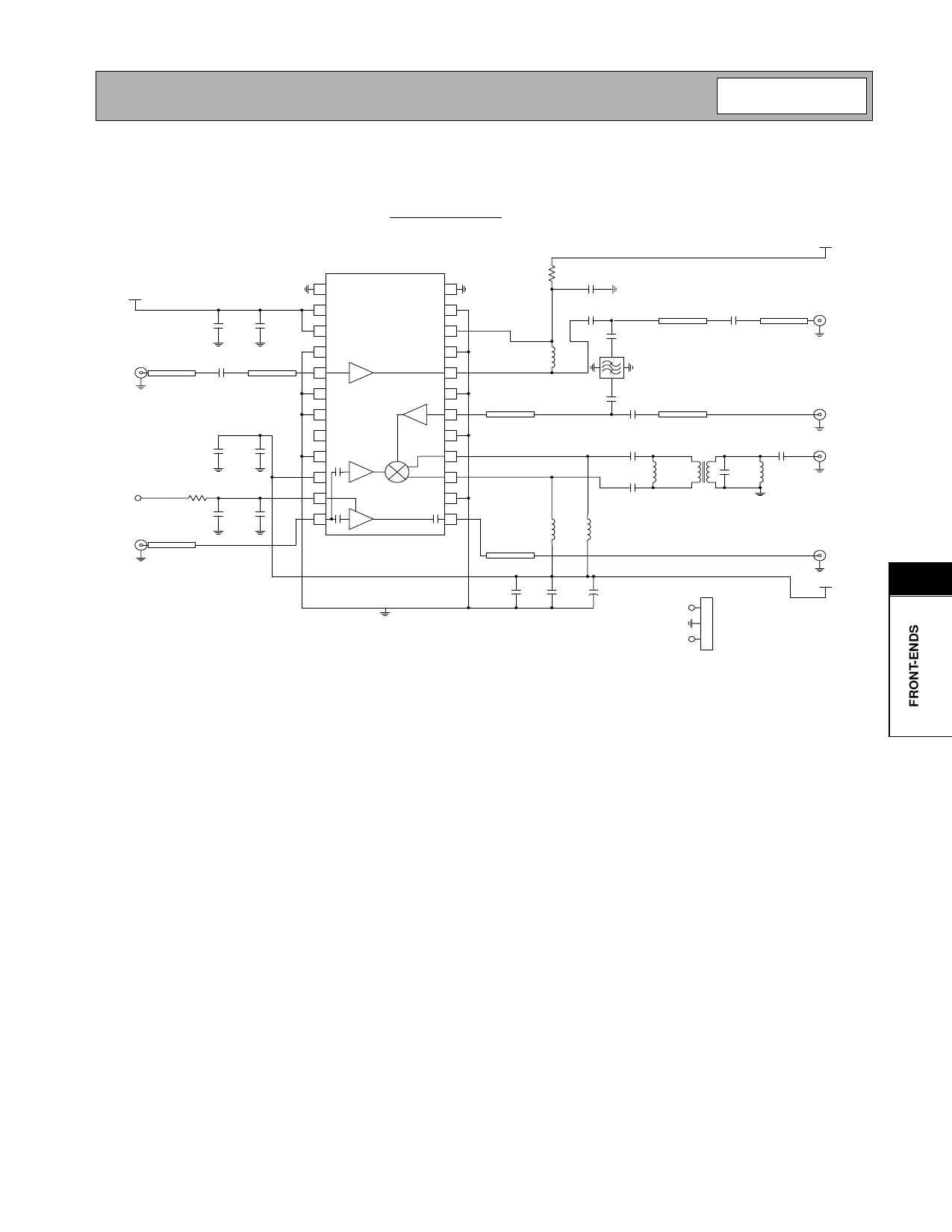
RF2486
Evaluation Board Schematic
1.96GHz, 210MHz IF
(Download Bill of Materials from www.rfmd.com.)
VCC
VCC
C10
1 nF
C5
22 pF
J1
LNA2 IN
50 Ω µstrip
C18
22 pF
**See Notes**
50 Ω µstrip
C12
22 pF
VCC
C6
1 nF
BUFF EN
J2
LO IN
R1
1 kΩ
C14
1 nF
50 Ω µstrip
C7
22 pF
1
2
3
4
5
6
7
8
9
10
11
12
2486400-
R2*
SAT
C3
22 pF
24
**See Notes**
C4
C1a
23
1.5 pF
50 Ω µstrip
22 pF
50 Ω µstrip
22
C1*
22 pF
21
L1
2.7 nH
FL1*
20
19
50 Ω µs trip
18
17
16
15
14
C2*
22 pF
C2a
22 pF
C16
100 pF
C17
100 pF
50 Ω µs trip
**See Notes**
T1
L5
220 nH
TOKO
C8
5 pF
C11
L4
1.0 pF 47 nH
13
L3
L2
470 nH 470 nH
50 Ω µs trip
VCC
Gnd
*C om ponents not norm ally populated.
NOTES:
C11 selected to fine tune L4 for IF output match at 210 MHz.
R2 is norm ally not populated. For applications requiring additional LN A IP3, see the data sheet for
recom m ended resistance values.
C1a and C 2a are norm ally not populated. If C 1a and C2a are populated, the LNA and m ixer can be
tested independently. In this case, C 1 and C 2 should be rem oved.
To use the part w ith onboard filter, do not populate C 1a, and C 2a.
Use C1 and C2 instead. This w ill allow cascaded operation only.
C13
1 nF
C9
+ C15
22 pF
4.7 uF
P1
BUFFER ENABLE
1
2
VCC
3
J6
LNA OUT
J5
M IXE R IN
J4
IF OUT
J3
LO OUT
VCC
8
Rev A7 010717
8-109
Share Link: 