LC89962M Ver la hoja de datos (PDF) - SANYO -> Panasonic
Número de pieza
componentes Descripción
Fabricante
LC89962M Datasheet PDF : 6 Pages
| |||
LC89962, LC89962M
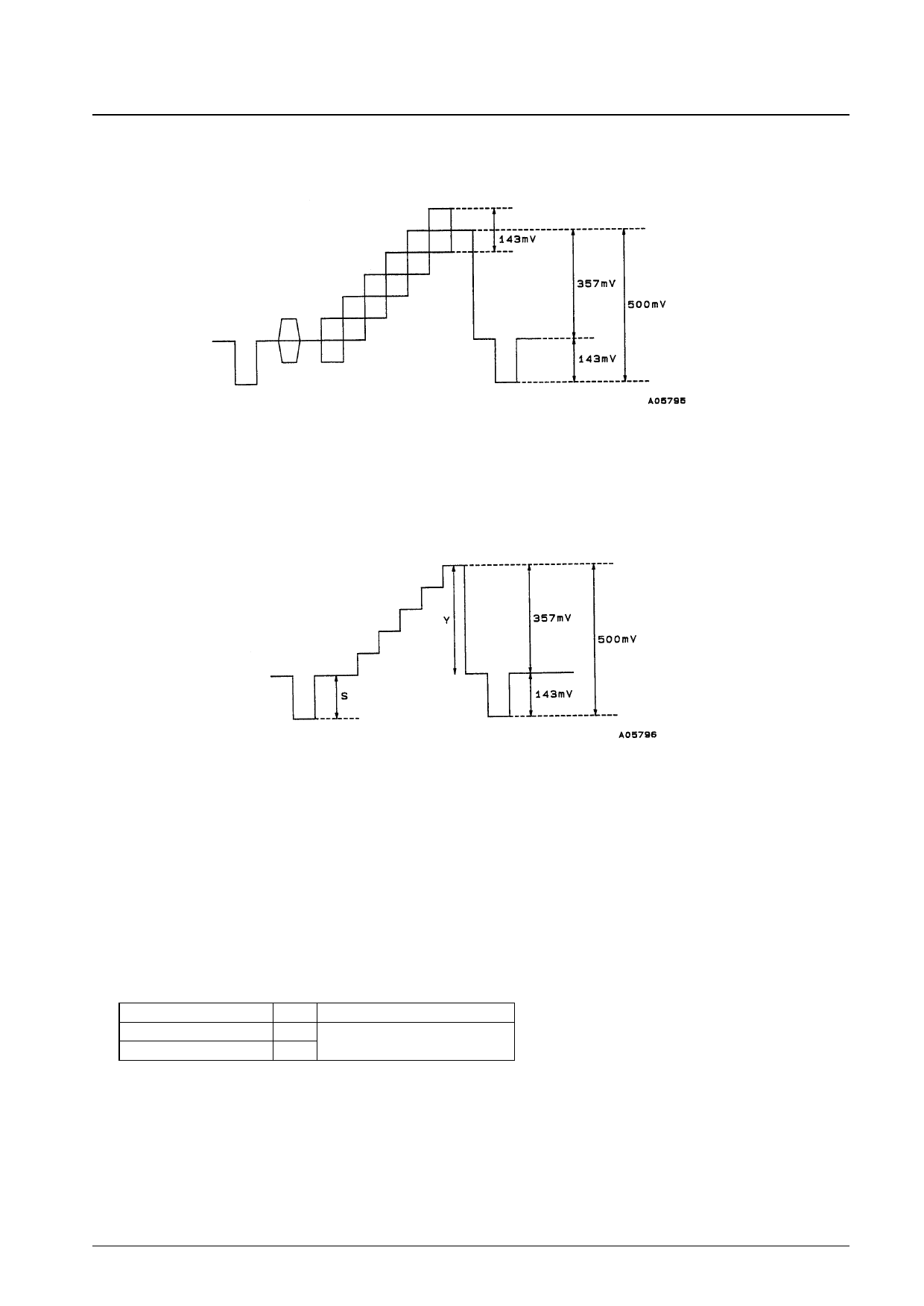
4. Measure the differential gain (DG) and differential phase (DP) using a vector scope with a 5-step function wave
input. (See the following figure.)
5. To measure LS, input a 5-step function wave and measure the ratio of the sync level (S) to the luminance level (Y).
LS
=
S [mV]
————
×
100
[%]
Y [mV]
6. To measure clock leakage (Lck), measure the 4fsc (14.3 MHz) component in the output signal with a spectrum
analyzer when no input signal is presented.
7. To measure the noise level (NO), measure the noise output in the OUT pin output when no input signal is present
with a video noise meter. Set up the noise meter with a 200-kHz high-pass filter, a 4.2-MHz low-pass filter, and
3.58-MHz trap filter.
8. The following formula is used to calculate the output impedance (ZO).
ZO
=
V1 [mVp-p] – V2 [mVp-p]
———————————
V2 [mVp-p]
×
500
[Ω]
Output signal symbol
V1
V2
SW3
a
b
Input signal
Sine wave: 200 kHz, 500 mV p-p
9. To measure the delay time (TD), measure the delay time of the output signal to the input signal. In this measurement,
the delay time associated with the low-pass filter must be excluded.
No. 5420-3/6
Share Link: 