BUL45 Ver la hoja de datos (PDF) - Motorola => Freescale
Número de pieza
componentes Descripción
Fabricante
BUL45 Datasheet PDF : 10 Pages
| |||
BUL45 BUL45F
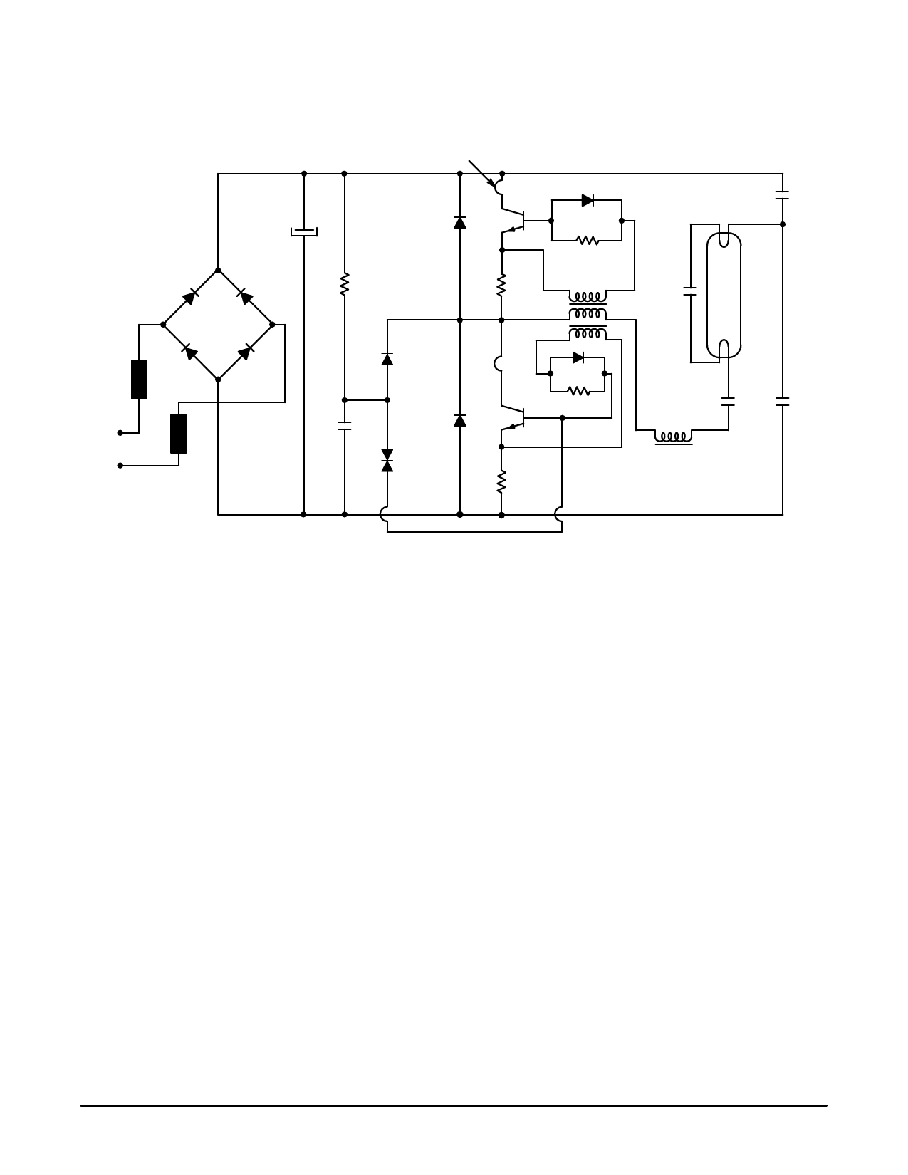
The BUL45/BUL45F Bipolar Power Transistors were
specially designed for use in electronic lamp ballasts. A
circuit designed by Motorola applications was built to
demonstrate how well these devices operate. The circuit and
detailed component list are provided below.
D10
D8
FUSE
CTN
AC LINE
220 V
COLLECTOR CURRENT SENSE
(USE EXTERNAL STRAPS)
22 µF 385 V
C1
MUR150
D3
Q1
IC
D5
47 Ω
D9
470 kΩ
1Ω
T1A
T1B
D7
D1 1N4007
IC Q2
D6
C2
MUR150
47 Ω
0.1 µF 100 V
D2
D4
1N5761
1Ω
1000 V
C5 400 V
0.1 µF
15 µF
C4
TUBE
C3 1000 V 400 V
L
10 nF C6 0.1 µF
5.5 mH
Components Lists
Q1 =
D1 =
D2 =
D3 =
D5 =
D7 =
CTN =
L=
T1 =
Q2 = BUL45 Transistor
1N4007 Rectifier
1N5761 Rectifier
D4 = MUR150
D6 = MUR105
D8 = D9 = D10 = 1N400
47 Ω @ 25°C
RM10 core, A1 = 400, B51 (LCC) 75 turns,
wire ∅ = 0.6 mm
FT10 toroid, T4A (LCC)
Primary: 4 turns
Secondaries: T1A: 4 turns
Secondaries: T1B: 4 turns
All resistors are 1/4 Watt, ±5%
R1 = 470 kΩ
R2 = R3 = 47 Ω
R4 = R5 = 1 Ω (these resistors are optional, and
might be replaced by a short circuit)
C1 = 22 µF/385 V
C2 = 0.1 µF
C3 = 10 nF/1000 V
C4 = 15 nF/1000 V
C5 = C6 = 0.1 µF/400 V
NOTES:
1. Since this design does not include the line input filter, it cannot be used “as–is” in a practical industrial circuit.
2. The windings are given for a 55 Watt load. For proper operation they must be re–calculated with any other loads.
Figure 22. Application Example
8
Motorola Bipolar Power Transistor Device Data
Share Link: 