SFH6345 Ver la hoja de datos (PDF) - Siemens AG
Número de pieza
componentes Descripción
Fabricante
SFH6345 Datasheet PDF : 3 Pages
| |||
Characteristics (TA=0° to 70°C, unless otherwise specified,typical values TA=25°C)
Description
Symbol Min. Typ. Max.
Emitter (IR GaAlAs)
Forward Voltage, IF=16 mA
Reverse Current, VR=3 V
Capacitance, VR=0 V, f=1 MHz
Thermal Resistance
Detector (Si Photodiode + Transistor)
VF
IR
C0
RthJA
1.6
1.9
0.5
10
75
700
Supply Current, Logic High
IF=0, VO (open), VCC=15 V, TA=25°C
IF=0, VO (open), VCC=15 V
Output Current, Output High
IF=0, VO (open), VCC=5.5 V, TA=25°C
IF=0, VO (open), VCC=15 V, TA=25°C
IF=0, VO (open), VCC=15 V
Capacitance, VCE=5 V, f=1 MHz
Thermal Resistance
Package
ICCH
IOH
CCE
RthJA
0.01 1
2
.003 0.5
.01
1
—
50
3
300
Coupling Capacitance
CC
Coupling Transfer Ratio
IC/IF
IF=16 mA, VO=0.4 V, VCC=4.5 V, TA=25°C
IF=16 mA, VO=0.5 V, VCC=4.5 V
Collector Emitter Saturation Voltage
VOL
IF=16 mA, IO=2.4 mA, VCC=4.5 V, TA=25°C
Supply Current, Logic Low
ICCL
IF=16 mA, VO open, VCC=15 V
0.6
19
30
15
—
0.1
0.4
80
200
Unit
V
µA
pF
°K/W
µA
µA
pF
°K/W
pF
%
V
µA
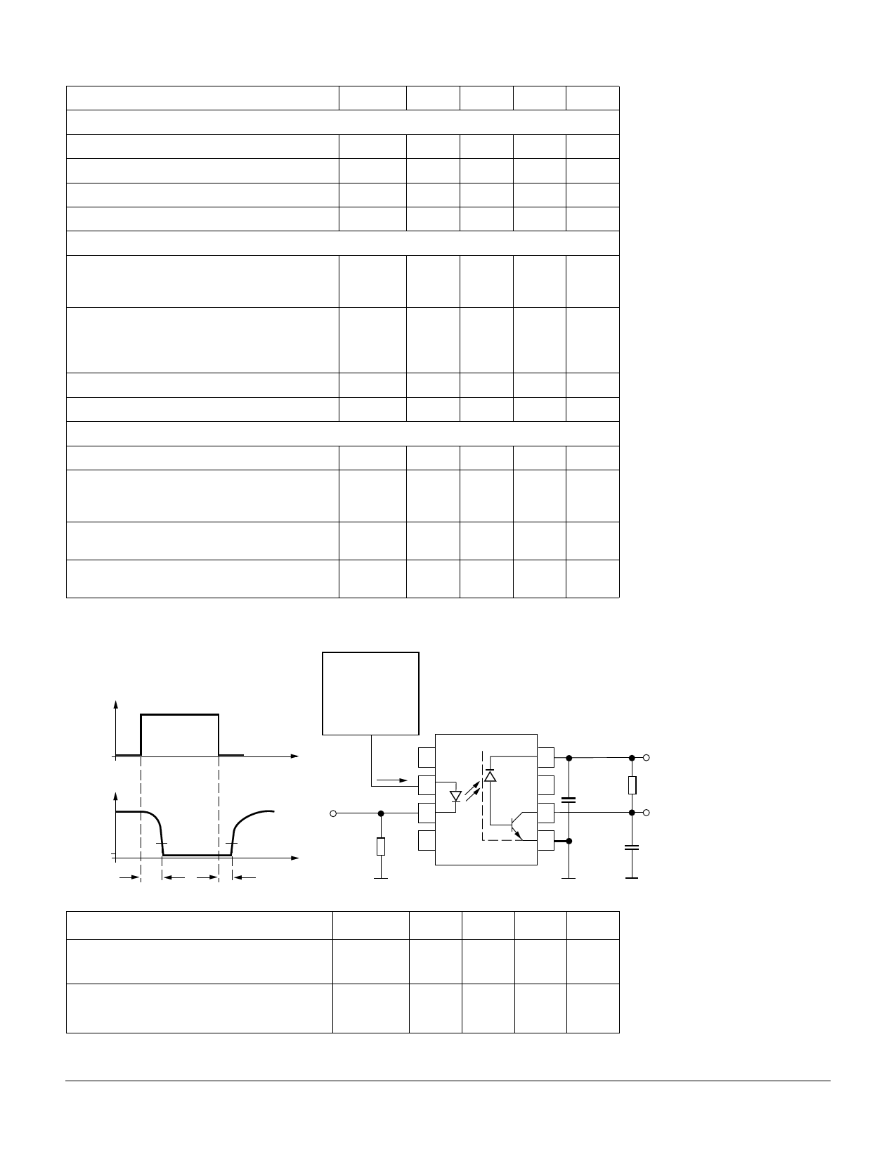
Switching Times (typ.)
IF
VO
VOL
tPHL
t
5V
1.5 V
t
tPLH
Pulse generator
ZO=50 Ω
tr,tf=5 ns
duty cycle 10%
t≤100 µs
1
IF
2
IF Monitor
3
100 Ω 4
8
5V
7
C=100 nF RL
6
VO
5
CL=15 pF
Description
Propagation Delay Time (High–Low)
IF=16 mA, VCC=5 V, RL=1.9 kΩ, TA=25°C
Propagation Delay Time (Low–High)
IF=16 mA, VCC=5 V, RL=1.9 kΩ, TA=25°C
Symbol
tPHL
tPLH
Min.
Typ.
0.3
Max.
0.8
Unit
µs
0.3
0.8
µs
5–280
SFH6345
Share Link: 