M34250M2 Ver la hoja de datos (PDF) - Renesas Electronics
Número de pieza
componentes Descripción
Fabricante
M34250M2 Datasheet PDF : 59 Pages
| |||
MITSUBISHI MICROCOMPUTERS
4250 Group
SINGLE-CHIP 4-BIT CMOS MICROCOMPUTER
(4) Internal state during an interrupt
The internal state of the microcomputer during an in-
terrupt is as follows (Figure 14).
• Program counter (PC)
An interrupt address is set in program counter. The
address to be executed when returning to the main
routine is automatically stored in the stack register
(SK).
• Interrupt enable flag (INTE)
INTE flag is cleared to “0” so that interrupts are disa-
bled.
• Interrupt request flag
Only the request flag for the current interrupt source
is cleared to “0.”
• Data pointer, carry flag and skip flag
The contents of these pointer and flags are stored
automatically in the interrupt stack register (SDP).
• Program counter (PC) ........... Each interrupt address
• Stack register (SK)
The address of main routine to
be executed when returning
• Interrupt enable flag (INTE) ...... 0 (Interrupt disabled)
• Interrupt request flag (only the flag for the current interrupt
source) ...................................................................... 0
• Data pointer, carry flag, skip flag
......... Stored in the interrupt stack register (SDP) automatically
Fig. 14 Internal state when interrupt occurs
(5) Interrupt processing
When an interrupt occurs, a program at an interrupt
address is executed after branching a data store se-
quence to stack register. Write the branch instruction
to an interrupt service routine at an interrupt address.
Use the RTI instruction to return to main routine.
Interrupt enabled by executing the EI instruction is per-
formed after executing 1 instruction (just after the next
instruction is executed). Accordingly, when the EI in-
struction is executed just before the RTI instruction,
interrupts are enabled after returning the main routine.
(Refer to Figure 13)
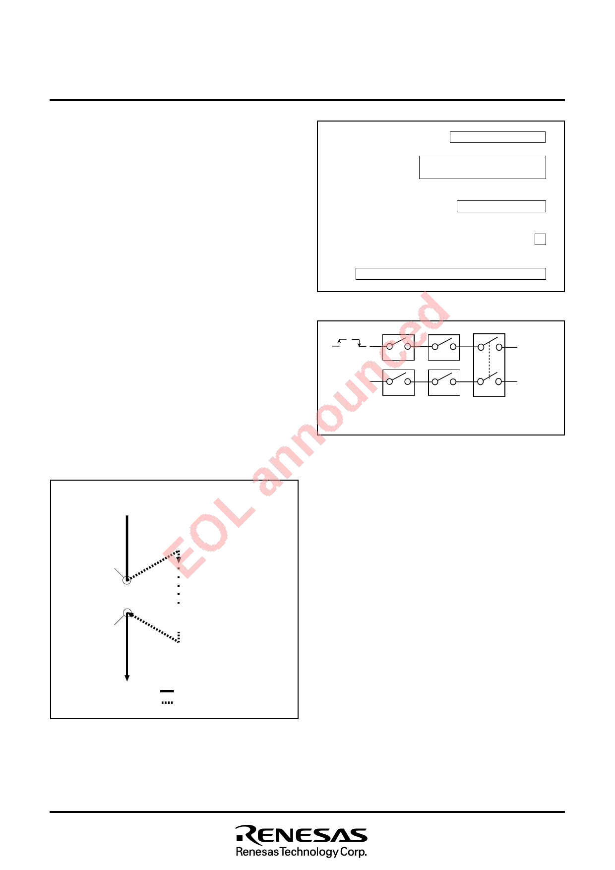
INT pin
(L→H or
H→L input)
EXF0
V10
Timer 1
underflow
T1F
V11
Activated Request flag Enable
condition (state retained) bit
Fig. 15 Interrupt system diagram
Address 0
in page 1
Address 2
in page 1
Enable
flag
Main routine
Interrupt
occurs
Interrupt
service routine
EI
Interrupt
RTI
is enabled
: Interrupt enabled state
: Interrupt disabled state
Fig. 13 Program example of interrupt processing
16
Share Link: 