AAT1106 Ver la hoja de datos (PDF) - Skyworks Solutions
Número de pieza
componentes Descripción
Fabricante
AAT1106 Datasheet PDF : 19 Pages
| |||
Part
Sumida
CR43
Sumida
CDRH4D18
Toko
D312C
L (μH)
1.4
2.2
3.3
4.7
1.0
2.2
3.3
4.7
1.5
2.2
3.3
4.7
Max
DCR
(m)
56.2
71.2
86.2
108.7
4.5
75
110
162
120
140
180
240
Rated DC
Current
(A)
2.52
1.75
1.44
1.15
1,72
1.32
1.04
0.84
1.29
1.14
0.98
0.79
Size
WxLxH
(mm)
4.5x4.0x3.5
4.7x4.7x2.0
3.6x3.6x1.2
Table 2: Typical Surface Mount Inductors.
For output voltages above 2.0V, when light-load effi-
ciency is important, the minimum recommended induc-
tor size is 2.2μH. For optimum voltage-positioning load
transients, choose an inductor with DC series resistance
in the 50m to 150m range. For higher efficiency at
heavy loads (above 200mA), or minimal load regulation
(with some transient overshoot), the resistance should
be kept below 100m. The DC current rating of the
inductor should be at least equal to the maximum load
current plus half the ripple current to prevent core satu-
ration (600mA + 105mA). Table 2 lists some typical
surface mount inductors that meet target applications
for the AAT1106.
Manufacturer's specifications list both the inductor DC
current rating, which is a thermal limitation, and the
peak current rating, which is determined by the satura-
tion characteristics. The inductor should not show any
appreciable saturation under normal load conditions.
Some inductors may meet the peak and average current
ratings yet result in excessive losses due to a high DCR.
Always consider the losses associated with the DCR and
its effect on the total converter efficiency when selecting
an inductor. For example, the 2.2μH CR43 series induc-
tor selected from Sumida has a 71.2mΩ DCR and a
1.75ADC current rating. At full load, the inductor DC loss
is 25mW which gives a 2.8% loss in efficiency for a
600mA, 1.5V output.
Slope Compensation
The AAT1106 step-down converter uses peak current
mode control with a unique adaptive slope compensation
scheme to maintain stability with lower value inductors
DATA SHEET
AAT1106
600mA Step-Down Converter
for duty cycles greater than 50%. Using lower value
inductors provides better overall efficiency and also
makes it easier to standardize on one inductor for differ-
ent required output voltage levels. In order to do this
and keep the step-down converter stable when the duty
cycle is greater than 50%, the AAT1106 separates the
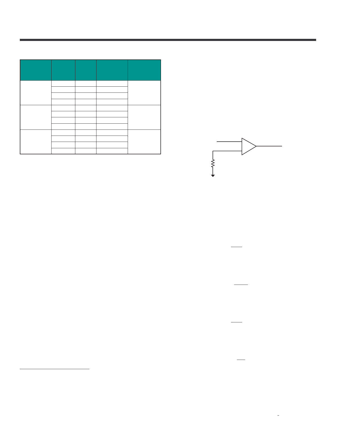
slope compensation into 2 phases. The required slope
compensation is automatically detected by an internal
circuit using the feedback voltage VFB before the error
amp comparison to VREF.
VREF
VFB
Error Amp
When below 50% duty cycle, the slope compensation is
0.284A/μs; but when above 50% duty cycle, the slope
compensation is set to 1.136A/μs. The output inductor
value must be selected so the inductor current down slope
meets the internal slope compensation requirements.
Below 50% duty cycle, the slope compensation require-
ment is:
m = 1.25 = 0.284A/µs
2·L
Therefore:
L = 0.625 = 2.2µH
m
Above 50% duty cycle,
m = 5 = 1.136A/µs
2·L
Therefore:
L = 2.5 = 2.2µH
m
With these adaptive settings, a 2.2μH inductor can be
used for all output voltages from 0.6V to 5V.
Skyworks Solutions, Inc. • Phone [781] 376-3000 • Fax [781] 376-3100 • sales@skyworksinc.com • www.skyworksinc.com
12
201970B • Skyworks Proprietary Information • Products and Product Information are Subject to Change Without Notice. • March 15, 2013
Share Link: 