MAX3679AEVKIT Ver la hoja de datos (PDF) - Maxim Integrated
Número de pieza
componentes Descripción
Fabricante
MAX3679AEVKIT Datasheet PDF : 9 Pages
| |||
MAX3679A Evaluation Kit
Quick Start
For evaluation of the MAX3679A, configure the EV kit as
follows:
1) Determine which output is going to be evaluated and
connect to the test equipment through SMA cables.
Be sure not to leave any outputs unterminated (i.e.,
place 50I terminators on all unused outputs).
2) Connect a +3.3V power supply to J48 (VCC) and J2
(GND). Set the current limit to 200mA.
3) If the on-board crystal is used, set IN_SEL to HIGH.
4) Use Table 2 to set the output divider switches to
achieve the output frequency desired.
5) Enable the output under test by setting the related
output-enable switch (Qx_OE) HIGH.
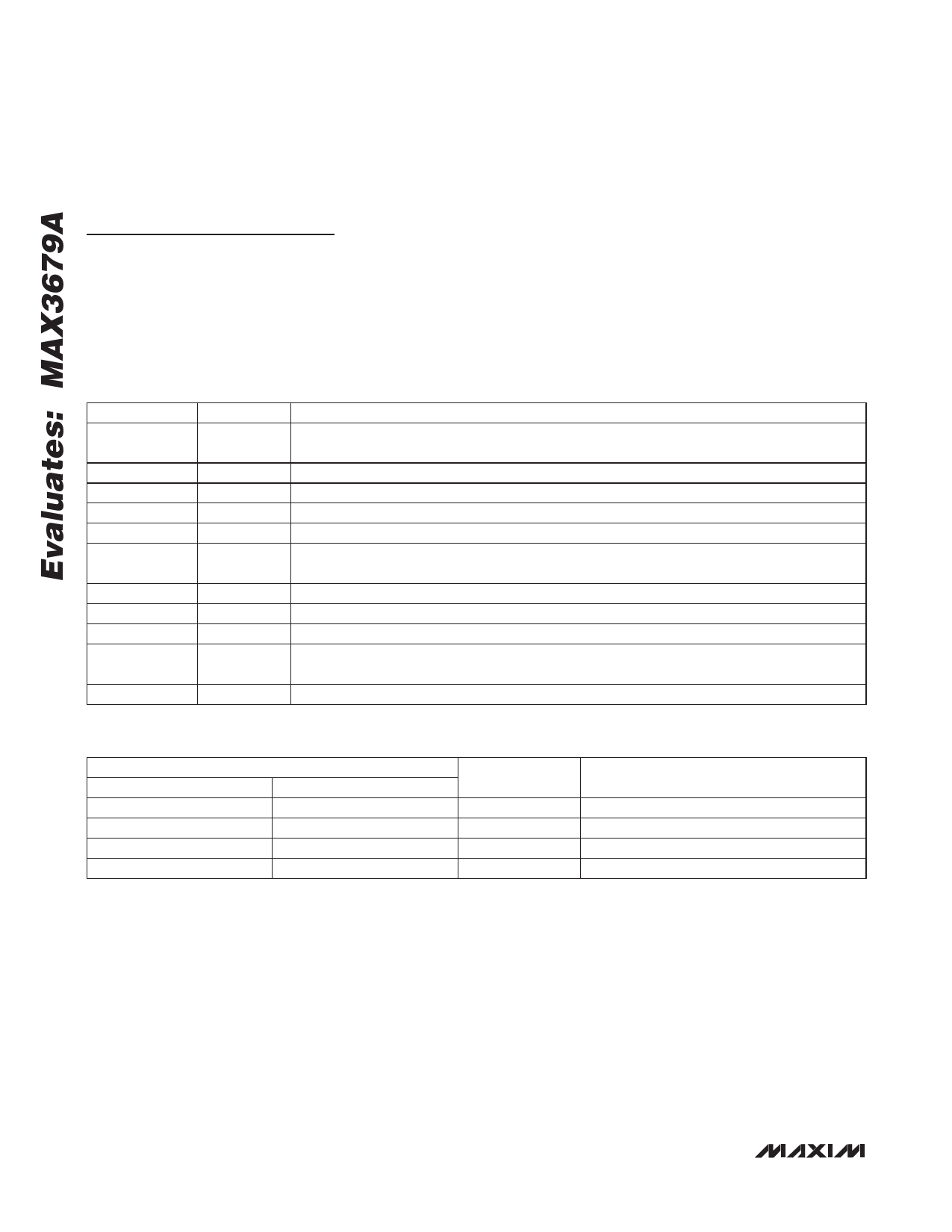
Table 1. Adjustment and Control Descriptions (see Quick Start first)
COMPONENT
J4
NAME
INDUCTOR
SHUNT
FUNCTION
J4 shunts the power-supply inductor. Normal operation is J4 shunted.
SW1
SW2
SW3
SW4
SELB1
SELB0
SELA1
QAC_OE
SW1 and SW2 set the output divider for the QB outputs. See Table 2 for more information.
SW1 and SW2 set the output divider for the QB outputs. See Table 2 for more information.
SW3 and SW11 set the output divider for the QA outputs. See Table 2 for more information.
Set HIGH to enable the LVCMOS output, QA_C. Set LOW to disable QA_C.
SW6
BYPASS
Set LOW to bypass the PLL. Set HIGH to engage the PLL. Note that when the PLL is
bypassed the output dividers are automatically set to divide by 1.
SW9
SW11
SW12
SW13
QA_OE
SELA0
QB1_OE
IN_SEL
Set HIGH to enable LVPECL output QA. Set LOW to force a logic zero at QA.
SW3 and SW11 set the output divider for the QA outputs. See Table 2 for more information.
Set HIGH to enable LVPECL output QB1. Set LOW to force a logic zero at QB1.
Set HIGH to select the crystal as the frequency source. Set LOW to select the REF_IN as the
frequency source.
SW15
QB0_OE Set HIGH to enable LVPECL output QB0. Set LOW to force a logic zero at QB0.
Table 2. Output Divider Settings
SELA1/SELB1
LOW
HIGH
HIGH
LOW
INPUT
SELA0/SELB0
LOW
LOW
HIGH
OPEN
NA/NB DIVIDER
÷2
÷4
÷5
÷10
OUTPUT FREQUENCY
(25MHz CRYSTAL)
312.5
156.25
125
62.5
2 _______________________________________________________________________________________
Share Link: 