LCX007BKA Ver la hoja de datos (PDF) - Sony Semiconductor
Número de pieza
componentes Descripción
Fabricante
LCX007BKA Datasheet PDF : 25 Pages
| |||
LCX007BKA
2. Optical Transmittance
Optical Transmittance (T) is given by the following formula (2).
L (White)
T=
× 100 [%] ... (2)
Luminance of Back Light
L (White) is the same expression as defined in the ‘Contrast Ratio’ section.
3. Chromaticity
Chromaticity of the panels are measured by System I. Raster modes of each color are defined by the
representations at the input signal amplitude conditions shown in the table below. System I uses
Chromaticity of x and y on the CIE standards here.
Signal amplitudes (VAC) supplied to each input
R input
G input
B input
R
0.5
4.5
4.5
G
4.5
0.5
4.5
B
4.5
4.5
0.5
(Unit: V)
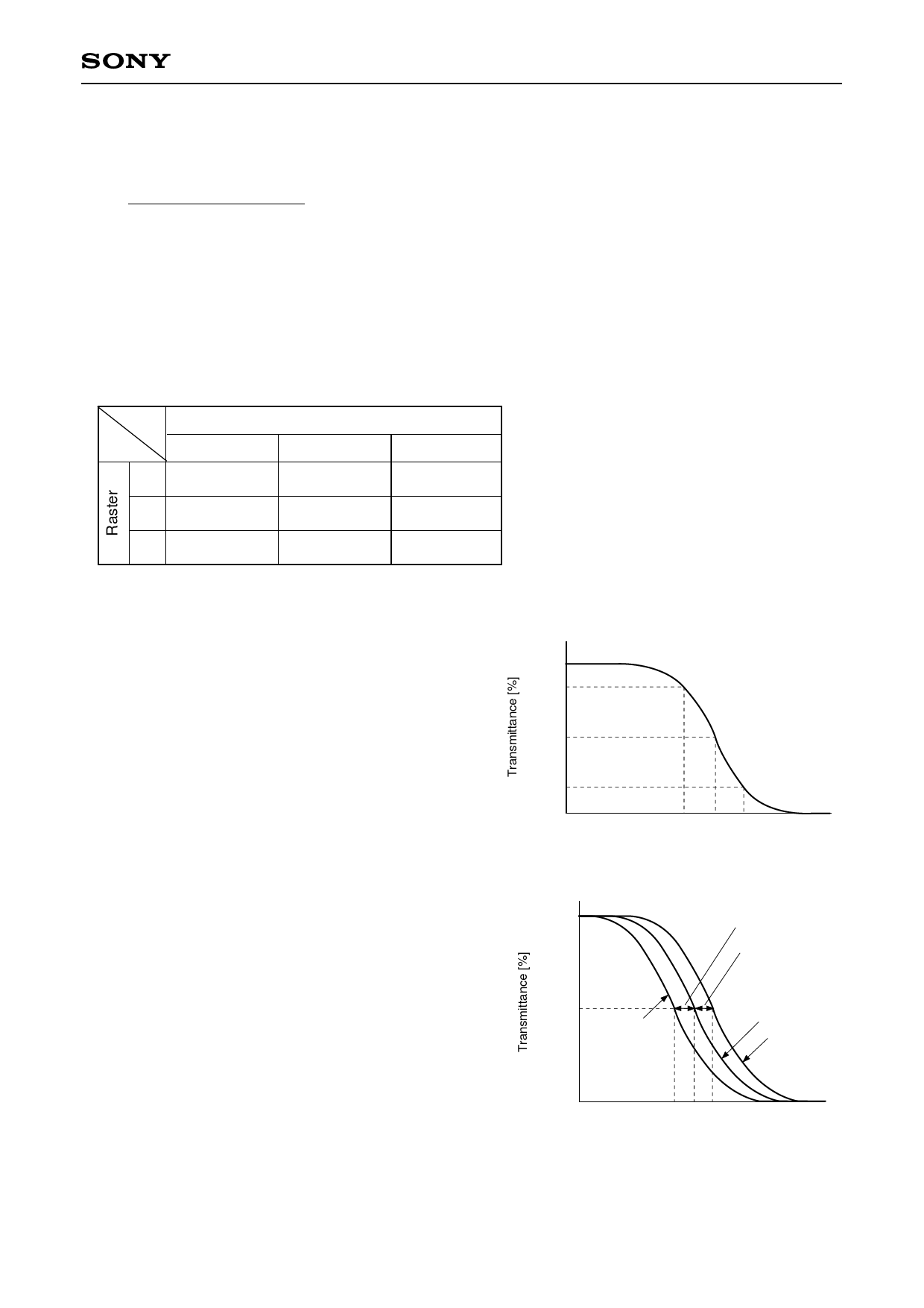
4. V-T Characteristics
V-T characteristics, the relationship between signal
amplitude and the transmittance of the panels, are
measured by System II. V90, V50 and V10 correspond to
the each voltage which defines 90%, 50% and 10% of
transmittance respectively.
5. Half Tone Color Reproduction Range
Half tone color reproduction range of the LCD panels is
characterized by the defferences between the V-T
characteristics of R, G and B. The differences of these
V-T characteristics are measured by System II. System
II defines signal voltages of each R, G, B raster modes
which corresponds to 50% of transmittance, V50R, V50G
and V50B respectively. V50RG and V50BG, the voltage
differences between V50R and V50G, V50B and V50G, are
simply given by the following formula (3) and (4)
respectively.
V50RG = V50R – V50G ... (3)
V50BG = V50B – V50G ... (4)
– 12 –
90
50
10
V90 V50 V10
VAC – Signal amplitude [V]
100
50
R raster
V50RG
V50BG
G raster
B raster
0
V50R V50B
V50G
VAC – Signal amplitude [V]
Share Link: 