LK112SXX48 Ver la hoja de datos (PDF) - STMicroelectronics
Número de pieza
componentes Descripción
Fabricante
LK112SXX48 Datasheet PDF : 18 Pages
| |||
Pin configuration
2
Pin configuration
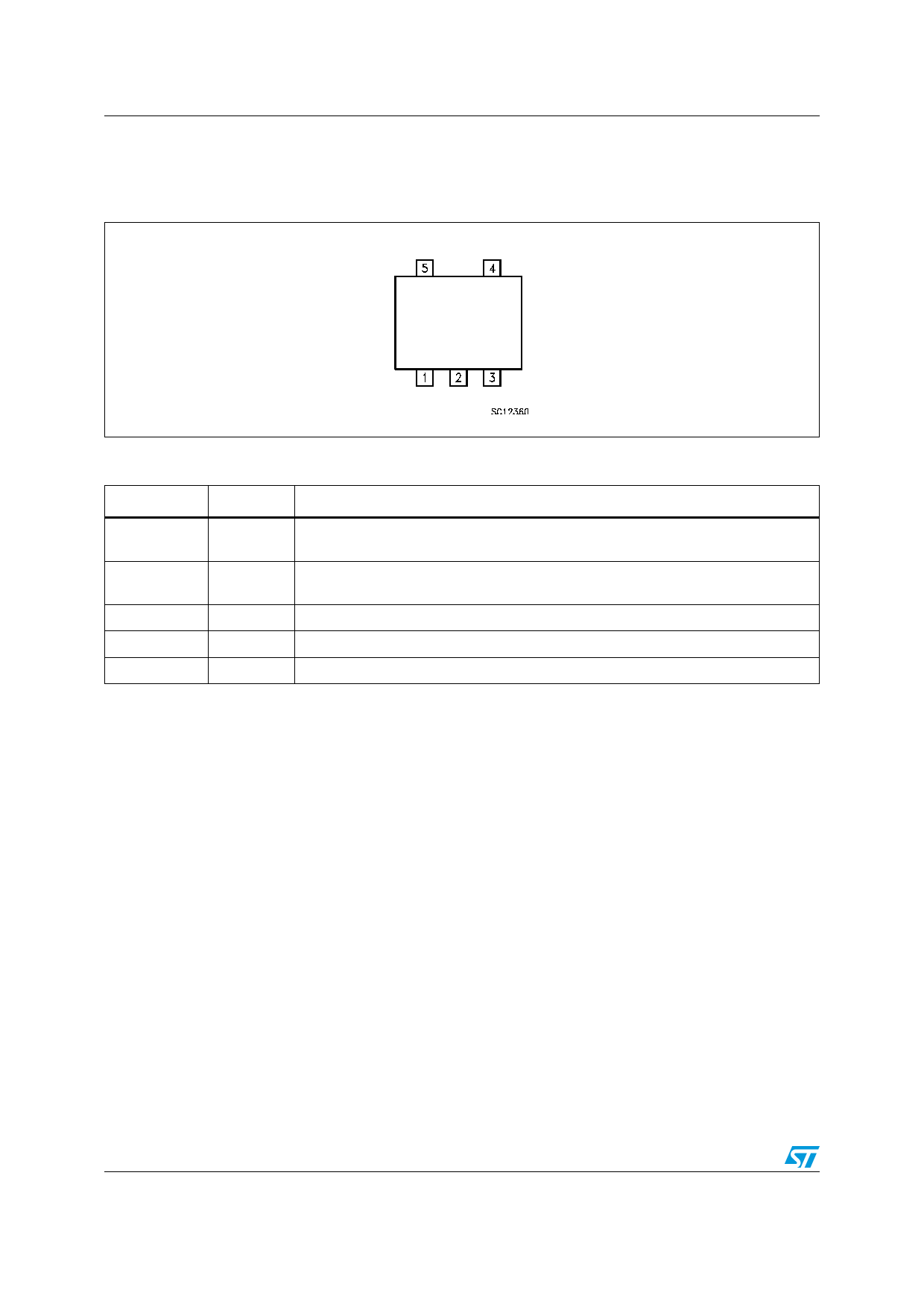
Figure 2. Pin connection (top view)
LK112Sxx
Table 2. Pin description
Pin n°
Symbol
Note
1
SHDN
Shutdown Input: Disables the regulator when is connected to GND or to positive
voltage less than 0.6 V
2
GND
Ground Pin: Internally connected to the die attach flag to decrease the total thermal
resistance and increase the package ability to dissipate power.
3
Bypass Bypass Pin: Bypass with 0.1 µF to improve the VREF thermal noise performances.
4
OUT Output port
5
IN
Input port
4/18
Share Link: 