87C196LA Ver la hoja de datos (PDF) - Intel
Número de pieza
componentes Descripción
Fabricante
87C196LA Datasheet PDF : 21 Pages
| |||
87C196LA — AUTOMOTIVE
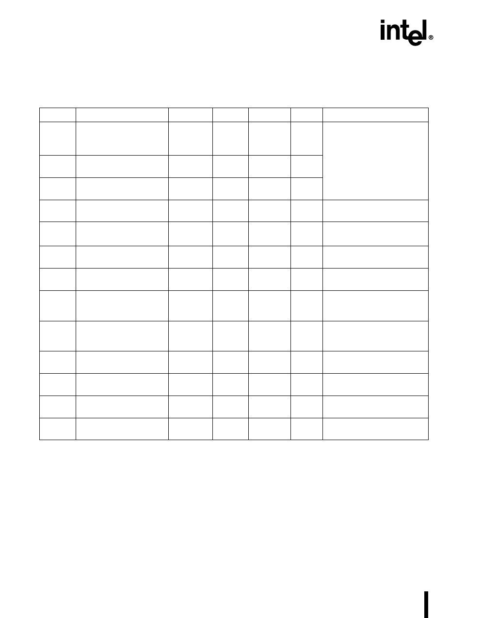
5.1 DC Characteristics
Symbol
Table 6. DC Characteristics at VCC = 4.5V to 5.5V
Parameter
Min Typical Max Units Test Conditions (Note 1)
ICC
VCC supply current
(–40° C to +125° C
ambient)
ICC1
Active mode supply cur-
rent (typical)
FXTAL1 = 20 MHz,
50
TBD
mA VCC = VPP = VREF = 5.5V
(While device is in reset)
50
mA
IREF
A/D reference supply
current
2
TBD
mA
IIDLE
Idle mode current
IPD
Powerdown mode
current
15
TBD
mA FXTAL1 = 20 MHz,
VCC = VPP = VREF = 5.5V
50
TBD
µA VCC = VPP = VREF = 5.5V
(Note 2)
VIL
Input low voltage
(all pins)
– 0.5V
0.3 VCC
V
VIH
Input high voltage (all
0.7 VCC
pins)
VCC + 0.5 V (Note 3)
VOL
Output low voltage
(outputs configured as
complementary)
VOH
Output high voltage
VCC – 0.3
(outputs configured as VCC – 0.7
complementary)
VCC – 1.5
ILI
Input leakage current
(standard inputs)
0.3
0.45
1.5
±8
V IOL = 200 µA (Notes 4, 5)
V IOL = 3.2 mA
V IOL = 7.0 mA
V IOH = – 200 µA (Notes 4, 5)
V IOH = – 3.2 mA
V IOH = – 7.0 mA
µA VSS ≤ VIN ≤ VCC (Note 6)
ILI1
Input leakage current
(port 0—A/D inputs)
±1
µA VSS ≤ VIN ≤ VREF
IIH
Input high current (NMI
pin only)
+175
µA VSS ≤ VIN ≤ VCC
VOL2
Output low voltage in
reset
1
V IOL = 6 µA (Notes 7, 8)
NOTES:
1. Device is static and should operate below 1 Hz, but is tested only down to 4 MHz with the PLL
enabled. With the PLL bypassed, the device is tested only down to 8MHz.
2. Typicals are based on a limited number of samples and are not guaranteed. The values listed are at
room temperature and VREF = VCC = 5.5V.
3. VIH max for port 0 is VREF + 0.5V.
4. All bidirectional pins when configured as complementary outputs.
5. Maximum IOLor IOH currents per pin will be characterized and published at a later date. Target values
are ± 10 mA.
6. Standard input pins include XTAL1, EA#, RESET#, and ports 1–6 when configured as inputs.
7. All bidirectional pins except P5.1/INST and P2.7/CLKOUT, which are excluded because they are not
weakly pulled low in reset. Bidirectional pins include ports 1–6.
8. This specification is not tested in production and is based upon theoretical estimates and/or product
characterization.
16
PRODUCT PREVIEW
Share Link: 