MAX4943ELAT Ver la hoja de datos (PDF) - Maxim Integrated
Número de pieza
componentes Descripción
Fabricante
MAX4943ELAT Datasheet PDF : 10 Pages
| |||
Overvoltage-Protection Controllers with
Internal FET
GP GATE Drive
When the input voltage goes above ground, GP pulls
low and turns on the pFET. An internal clamp protects
the pFET by ensuring that the GP to IN voltage does not
exceed 19V (max) when the input (IN) rises to +28V.
Undervoltage Lockout (UVLO)
The MAX4944L/MAX4945L/MAX4946/MAX4949 have a
2.45V (typ) undervoltage-lockout threshold (VUVLO),
while the remaining devices have a 4.15V (typ) VUVLO
threshold. When VIN is less than VUVLO, ACOK is high
impedance.
Overvoltage-Lockout Thresholds (OVLO)
The MAX4943 has a 7.4V (typ) overvoltage threshold
(VOVLO), the MAX4944_ has a 6.35V (typ) VOVLO
threshold, the MAX4945_ has a 5.80V (typ) VOVLO
threshold, the MAX4946 has a 4.56V (typ) VOVLO
threshold, and the MAX4949 has a 8.90V (typ) VOVLO
threshold. When VIN is greater than OVLO, ACOK is
high impedance.
ACOK
ACOK is an active-low, open-drain output that asserts
low when VUVLO < VIN < VOVLO for the 30ms (typ) peri-
od. Connect a pullup resistor from ACOK to the logic
I/O voltage of the host system. During a short-circuit
fault, ACOK may deassert due to VIN not being in the
valid operating voltage range.
Thermal-Shutdown Protection
The MAX4943–MAX4946/MAX4949 feature thermal-shut-
down circuitry. The internal switch turns off when the junc-
tion temperature exceeds +175°C (typ) and immediately
goes into a fault mode. The device exits thermal shut-
down after the junction temperature cools by 40°C (typ).
Applications Information
IN Bypass Capacitor
For most applications, bypass IN to GND with a 1µF
ceramic capacitor as close as possible to the device to
enable ±15kV (HBM) ESD protection on the pin. If
±15kV is not required, there is no capacitor required at
IN. If the power source has significant inductance due
to long lead length, take care to prevent overshoots
due to the LC tank circuit and provide protection if nec-
essary to prevent exceeding the +30V absolute maxi-
mum rating on IN.
Reverse Polarity Protection
The optional external pFET can provide reverse polarity
protection down to -28V (for a 30V pFET), if the protect-
tOFF
SWITCH ON
SWITCH ON
tRETRY
SWITCH OFF
CURRENT
THROUGH
SWITCH
ILIM
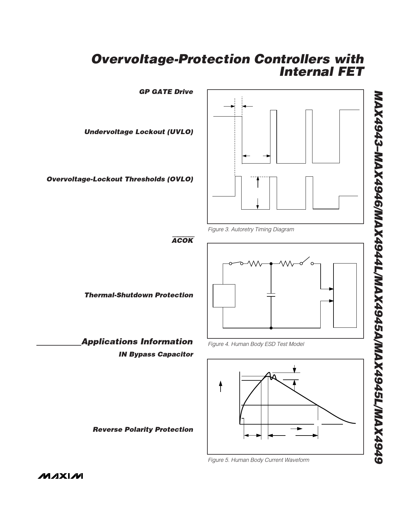
Figure 3. Autoretry Timing Diagram
RC
1MΩ
RD
1.5kΩ
CHARGE-CURRENT-
LIMIT RESISTOR
DISCHARGE
RESISTANCE
HIGH-
VOLTAGE
DC
SOURCE
Cs
100pF
STORAGE
CAPACITOR
DEVICE
UNDER
TEST
Figure 4. Human Body ESD Test Model
IP 100%
90%
AMPERES
36.8%
10%
0
0 tRL
Ir
PEAK-TO-PEAK RINGING
(NOT DRAWN TO SCALE)
TIME
tDL
CURRENT WAVEFORM
Figure 5. Human Body Current Waveform
_______________________________________________________________________________________ 7
Share Link: 