42568WP Ver la hoja de datos (PDF) - STMicroelectronics
Número de pieza
componentes Descripción
Fabricante
42568WP Datasheet PDF : 39 Pages
| |||
M24256-BW M24256-BR M24256-BF M24256-DR M24256-DF
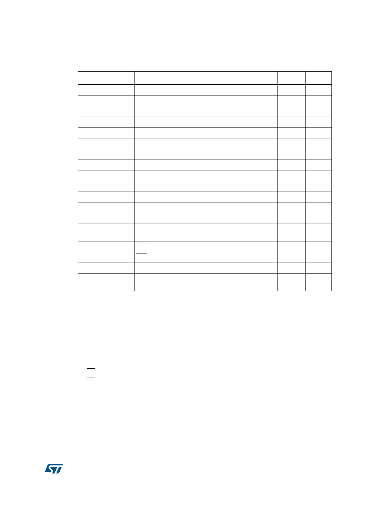
DC and AC parameters
Symbol Alt.
Table 17. 1 MHz AC characteristics
Parameter(1)
Min.
Max.
Unit
fC
tCHCL
tCLCH
tXH1XH2
tXL1XL2
tQL1QL2(3)
tDXCH
tCLDX
tCLQX(5)
tCLQV(6)
tCHDL
tDLCL
tCHDH
tDHDL
tWLDL(8)(3)
tDHWH(9)(3)
tW
tNS(3)
fSCL
tHIGH
tLOW
tR
tF
tF
tSU:DAT
tHD:DAT
tDH
tAA
tSU:STA
tHD:STA
tSU:STO
tBUF
tSU:WC
tHD:WC
tWR
Clock frequency
Clock pulse width high
Clock pulse width low
Input signal rise time
Input signal fall time
SDA (out) fall time
Data in setup time
Data in hold time
Data out hold time
Clock low to next data valid (access time)
Start condition setup time
Start condition hold time
Stop condition setup time
Time between Stop condition and next Start
condition
WC set up time (before the Start condition)
WC hold time (after the Stop condition)
Write time
Pulse width ignored (input filter on SCL and
SDA)
0
260
500
(2)
(2)
20(4)
50
0
100
-
250
250
250
500
0
1
-
-
1
-
-
(2)
(2)
120
-
-
-
450(7)
-
-
-
-
-
-
5
80(10)
MHz
ns
ns
ns
ns
ns
ns
ns
ns
ns
ns
ns
ns
ns
µs
µs
ms
ns
1. Only for devices identified by the process letter K (devices qualified at 1 MHz).
2. There is no min. or max. values for the input signal rise and fall times. It is however recommended by the
I²C specification that the input signal rise and fall times be less than 120 ns when fC < 1 MHz.
3. Characterized only, not tested in production.
4. With CL = 10 pF.
5. To avoid spurious Start and Stop conditions, a minimum delay is placed between SCL=1 and the falling or
rising edge of SDA.
6.
t0C.7LQVVCiCs,thaesstuimmein(gfrothmatththeefaRllbinugs
edge of
× Cbus
SCL) required by the SDA
time constant is within the
vbauluselisnesptoecriefiaecdhineiFthigeur r0e.313V.CC
or
7. 500 ns for the previous products.
8. WC=0 set up time condition to enable the execution of a WRITE command.
9. WC=0 hold time condition to enable the execution of a WRITE command.
10. 50 ns for previous products.
DocID6757 Rev 32
29/39
38
Share Link: 