ADM8693ANZ Ver la hoja de datos (PDF) - Analog Devices
Número de pieza
componentes Descripción
Fabricante
ADM8693ANZ Datasheet PDF : 20 Pages
| |||
ADM8690/ADM8691/ADM8692/ADM8693/ADM8695
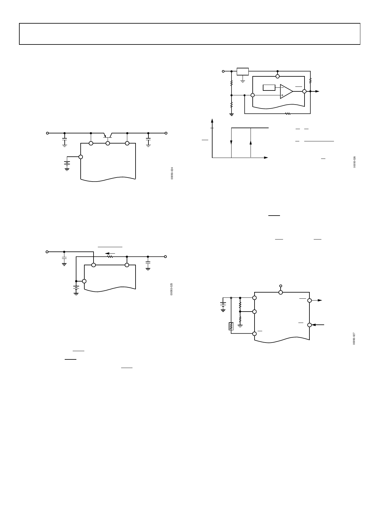
APPLICATION INFORMATION
INCREASING THE DRIVE CURRENT
If the continuous output current requirements at VOUT exceed
100 mA, or if a lower VCC – VOUT voltage differential is desired,
an external PNP pass transistor can be connected in parallel
with the internal transistor. The BATT ON output (ADM8691/
ADM8693/ADM8695) can directly drive the base of the
external transistor.
5V INPUT
POWER
0.1µF
PNP TRANSISTOR
0.1µF
BATTERY
VCC BATT
ON
VOUT
VBATT
ADM8691/
ADM8693/
ADM8695
Figure 24. Increasing the Drive Current
USING A RECHARGEABLE BATTERY FOR BACKUP
If a capacitor or a rechargeable battery is used for backup then
the charging resistor should be connected to VOUT because this
eliminates the discharge path that would exist during power-
down if the resistor is connected to VCC.
5V INPUT
POWER
0.1µF
RECHARGEABLE
BATTERY
I = VOUT – VBATT
R
R
VCC
VOUT
ADM869x
VBATT
0.1µF
Figure 25. Rechargeable Battery
ADDING HYSTERESIS TO THE POWER-FAIL
COMPARATOR
For increased noise immunity, hysteresis can be added to the
power-fail comparator. Because the comparator circuit is
noninverting, hysteresis can be added simply by connecting a
resistor between the PFO output and the PFI input as shown in
Figure 26. When PFO is low, Resistor R3 sinks current from the
summing junction at the PFI pin. When PFO is high, the series
combination of R3 and R4 sources current into the PFI
summing junction. This results in differing trip levels for the
comparator.
7V TO 15V
INPUT
POWER
R1
R2
5V
7805
VCC
1.3V
PFI
PFO
ADM869x
R3
R4
TO
MICROPROCESSOR
NMI
5V
PFO
( ) VH = 1.3V
1+
R1
R2
+
R1
R3
( ) VL = 1.3V
1+
R1
R2
– R1 (5V – 1.3V)
R3 (1.3V (R3 + R4))
0V
0V
VL
VH
VIN
ASSUMING R4 < < R3 THEN
( ) HYSTERESIS VH – VL = 5V
R1
R2
Figure 26. Adding Hysteresis to the Power-Fail Comparator
MONITORING THE STATUS OF THE BATTERY
The power-fail comparator can be used to monitor the status of
the backup battery instead of the power supply, if desired. This
is shown in Figure 27. The PFI input samples the battery voltage
and generates an active low PFO signal when the battery voltage
drops below a chosen threshold. It can be necessary to apply a
test load to determine the loaded battery voltage. This is done
under processor control using CEOUT. Because CEOUT is forced
high during the battery backup mode, the test load is not
applied to the battery while it is in use, even if the
microprocessor is not powered.
5V INPUT
POWER
BATTERY
20kΩ
OPTIONAL
TEST LOAD
VBATT
VCC
PFO
R1 10MΩ
LOW BATTERY
SIGNAL TO
PFI ADM869x
MICROPROCESSOR
I/O PIN
R2 10MΩ
CEOUT
CEIN
FROM
MICROPROCESSOR
I/O PIN APPLIES
TEST LOAD
TO BATTERY
Figure 27. Monitoring the Battery Status
Rev. B | Page 14 of 20
Share Link: 