RH56D-PCI Ver la hoja de datos (PDF) - Unspecified
Número de pieza
componentes Descripción
Fabricante
RH56D-PCI Datasheet PDF : 60 Pages
| |||
RH56D-PCI Modem Designer’s Guide
5.3 SERIAL EEPROM INTERFACE
The PCI Configuration Space Header and Power Management registers customizable fields are loaded from EEPROM during
Power On Reset and during D3 to D0 power transition soft reset. If the EEPROM is missing, default hard-coded values are
used. This section describes how the EEPROM content maps into the registers. The PCI Configuration Space Header and
Power Management information is used by the PC BIOS/Windows OS to find the driver for this board and also to find out the
extent PCI Power Management is typically supported on the modem board.
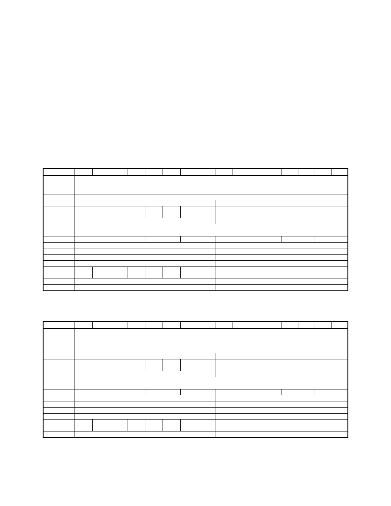
5.3.1 Supported EEPROM Sizes
Two EEPROM sizes are supported: 256 by 16 bit (e.g., 93LC66B) as shown in Table 5-7 and 128 by 16 bit (e.g., 93LC56B)
as shown in Table 5-8. The difference is the 256-word version supports modem default country selection from the EEPROM
and also supports CardBus designs, whereas the 128-word version supports neither.
The EEPROM text file used by the DOS4GW B2EPROM program utility lists the EEPROM content 8 bits per line in
hexadecimal format. The least significant 8 bits are listed first followed by the most significant 8 bits of the 16-bit word.
Address
00
01
02
03
04
05
06
07
08
09
0A
0B
0C
0D
0E
0F-FE
FF
7DEOH ((3520 &RQWHQW IRU :RUGV E\ %LWV SHU :RUG
15
14
13
12
11
10
Don’t Care
Max_Lat
PMC
bit 8
Sub-Class Code
PMC
bit 7
D0C
D3_ D3_
Cold Hot
D1C
D2C
D3 power consumed
D1 power consumed
D3 power dissipated
D1 power dissipated
D2
D1
D0 D2_
State
Don’t Care
Don’t Care
9
8
7
6
Device ID
Vendor ID
Subsystem Device ID
Subsystem Vendor ID
PMC PME
bit 6 DRV
CardBus CIS Pointer High
CardBus CIS Pointer Low
D3C
D0D
D1_ DSI
State
5
4
3
2
Min_Gnt
Class Code
Prog. I/F
D1D
D2D
D2 power consumed
D0 power consumed
D2 power dissipated
D0 power dissipated
Load CISRAM Count
Don’t Care
Don’t Care
1
0
D3D
Address
00
01
02
03
04
05
06
07
08
09
0A
0B
0C
0D
0E
0F-7F
7DEOH ((3520 &RQWHQW IRU :RUGV E\ %LWV SHU :RUG
15
14
13
12
11
10
Don’t Care
Max_Lat
PMC
bit 8
Sub-Class Code
PMC
bit 7
D0C
D3_ D3_
Cold Hot
D1C
D2C
D3 power consumed
D1 power consumed
D3 power dissipated
D1 power dissipated
D2
D1
D0 D2_
State
Don’t Care
9
8
7
6
Device ID
Vendor ID
Subsystem Device ID
Subsystem Vendor ID
PMC PME
bit 6 DRV
CardBus CIS Pointer High
CardBus CIS Pointer Low
D3C
D0D
D1_ DSI
State
5
4
3
2
Min_Gnt
Class Code
Prog. I/F
D1D
D2D
D2 power consumed
D0 power consumed
D2 power dissipated
D0 power dissipated
Load CISRAM Count
Don’t Care
1
0
D3D
5-6
Conexant
1213
Conexant Proprietary Information
Share Link: 