LTC1261C Ver la hoja de datos (PDF) - Linear Technology
Número de pieza
componentes Descripción
Fabricante
LTC1261C Datasheet PDF : 18 Pages
| |||
LTC1261
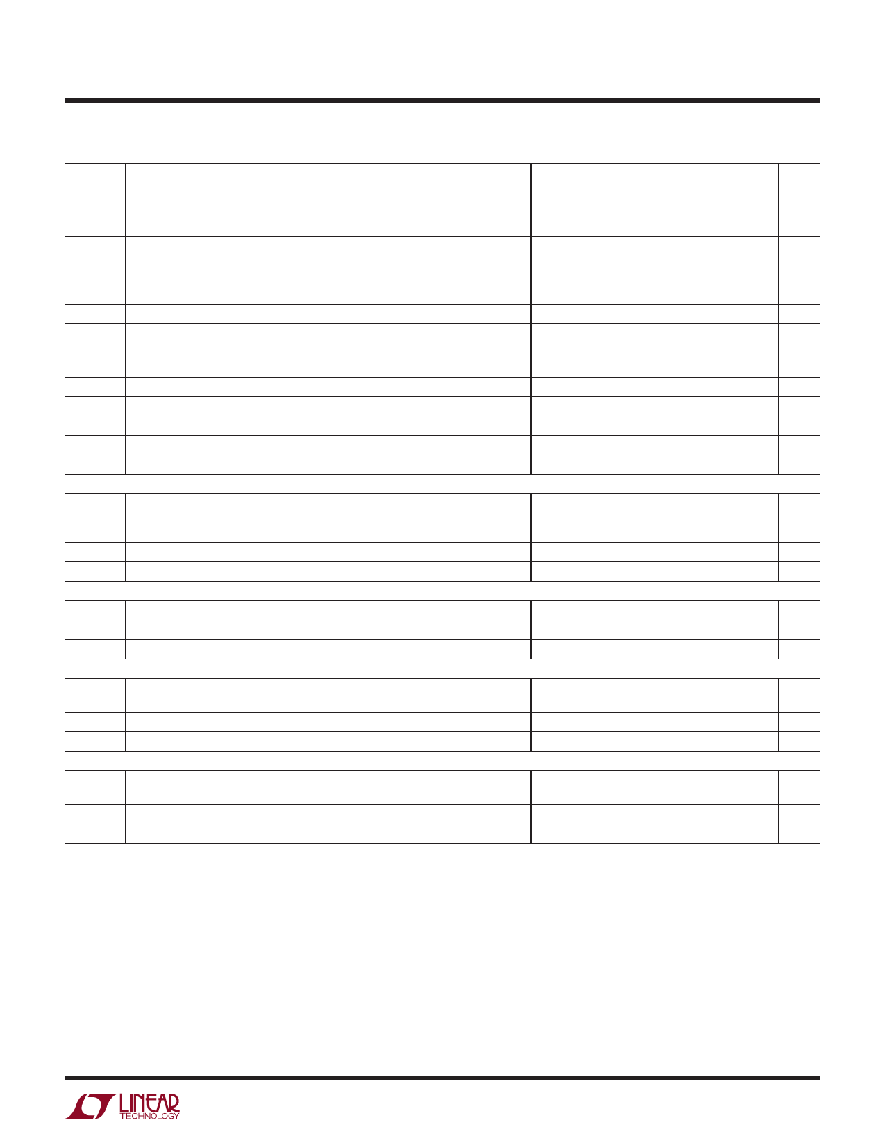
ELECTRICAL CHARACTERISTICS The l denotes the specifications which apply over the full operating
temperature range, otherwise specifications are at TA = 25°C. VCC = 3V to 6.5V unless otherwise specified.
SYMBOL PARAMETER
CONDITIONS
0°C ≤ TA ≤ 70°C
MIN TYP MAX
–40°C ≤ TA ≤ 85°C
(Note 7)
MIN TYP MAX
UNITS
VREF
Reference Voltage
l 1.20 1.24 1.28 1.20 1.24 1.28
V
IS
Supply Current
No Load, SHDN Floating, Doubler Mode l
No Load, SHDN Floating, Tripler Mode
l
600 1000
900 1500
600 1500
µA
900 2000
µA
No Load, VSHDN = VCC
l
5 20
5 20
µA
fOSC
Internal Oscillator Frequency
550
550
kHz
PEFF
Power Efficiency
65
65
%
VOL
REG Output Low Voltage
IREG = 1mA
l
0.1 0.8
0.1 0.8
V
IREG
REG Sink Current
VREG = 0.8V, VCC = 3.3V
VREG = 0.8V, VCC = 5.0V
l5
8
5
8
mA
l 8 15
8 15
mA
IADJ
Adjust Pin Current
VADJ = 1.24V
l
0.01 1
0.01 1
µA
VIH
SHDN Input High Voltage
l2
2
V
VIL
SHDN Input Low Voltage
l
0.8
0.8
V
IIN
SHDN Input Current
VSHDN = VCC
l
5 20
5 25
µA
tON
Turn-On Time
IOUT = 15mA
500
500
µs
Doubler Mode. VCC = 5V ±10%, C1 = 0.1µF, C2 = 0 (Note 4), COUT = 3.3µF unless otherwise specified.
∆VOUT
Output Regulation (Note 2)
–1.24V ≥ VOUT ≥ –4V, 0 ≤ IOUT ≤ 8mA
l
–1.24V ≥ VOUT ≥ –4V, 0 ≤ IOUT ≤ 7mA
l
–4V ≥ VOUT ≥ –5V, 0 ≤ IOUT ≤ 8mA (Note 6)
1
5
2
%
1
5
%
2
%
ISC
Output Short-Circuit Current VOUT = 0V
l
60 125
60 125
mA
VRIP
Output Ripple Voltage
IOUT = 5mA, VOUT = –4V
5
5
mV
LTC1261CS Only. Tripler Mode. VCC = 2.7V, C1 = C2 = 0.1µF (Note 4), COUT = 3.3µF unless otherwise specified.
∆VOUT
Output Regulation
–1.24V ≥ VOUT ≥ –4V, 0 ≤ IOUT ≤ 5mA
l
1
5
1
5
%
ISC
Output Short-Circuit Current VOUT = 0V
l
60 125
60 125
mA
VRIP
Output Ripple Voltage
IOUT = 5mA, VOUT = –4V
5
5
mV
LTC1261CS Only. Tripler Mode. VCC = 3.3V ±10%, C1 = C2 = 0.1µF (Note 4), COUT = 3.3µF unless otherwise specified.
∆VOUT
Output Regulation (Note 2) –1.24V ≥ VOUT ≥ –4.5V, 0 ≤ IOUT ≤ 6mA
l
–4.5V ≥ VOUT ≥ –5V, 0 ≤ IOUT ≤ 3.5mA
l
1
5
2
5
1
5
%
2
%
ISC
Output Short-Circuit Current VOUT = 0V
l
35 75
35 75
mA
VRIP
Output Ripple Voltage
IOUT = 5mA, VOUT = –4V
5
5
mV
LTC1261CS Only. Tripler Mode. VCC = 5V ±10%, C1 = C2 = 0.1µF (Note 4), COUT = 3.3µF unless otherwise specified.
∆VOUT
Output Regulation
–1.24V ≥ VOUT ≥ –4V, 0 ≤ IOUT ≤ 12mA
l
–4V ≥ VOUT ≥ –5V, 0 ≤ IOUT ≤ 10mA
l
1
5
2
5
1
5
%
2
5
%
ISC
Output Short-Circuit Current VOUT = 0V
l
35 75
35 75
mA
VRIP
Output Ripple Voltage
IOUT = 5mA, VOUT = –4V
5
5
mV
Note 1: Stresses beyond those listed under Absolute Maximum Ratings
may cause permanent damage to the device. Exposure to any Absolute
Maximum Rating condition for extended periods may affect device
reliability and lifetime.
Note 2: All currents into device pins are positive; all currents out of device
pins are negative. All voltages are referenced to ground unless otherwise
specified.
Note 3: All typicals are given at TA = 25°C.
Note 4: C1 = C2 = 0.1µF means the specifications apply to tripler mode
where VCC – VOUT = 3VCC (LTC1261CS only; the LTC1261CS8 cannot be
connected in tripler mode) with C1 connected between C1+ and C1– and
C2 connected between C2+ and C2–. C2 = 0 implies doubler mode where
VCC – VOUT = 2VCC; for the LTC1261CS this means C1 connects from C1+
to C2– with C1– and C2+ floating. For the LTC1261CS8 in doubler mode,
C1 connects from C1+ to C1–; there are no C2 pins.
Note 5: Setting output to <–7V will exceed the absolute voltage maximum
rating with a 5V supply. With supplies higher than 5V, the output should
never be set to exceed VCC – 12V.
Note 6: For output voltages below –4.5V the LTC1261 may reach 50%
duty cycle and fall out of regulation with heavy load or low input voltages.
Beyond this point, the output will follow the input with no regulation.
Note 7: The LTC1261C is guaranteed to meet specifications from 0°C
to 70°C and is designed, characterized and expected to meet industrial
temperature limits, but is not tested at –40°C and 85°C. The LTC1261IS8
is guaranteed to meet specifications from –40°C and 85°C.
1261fb
For more information www.linear.com/LTC1261
3
Share Link: 